
Summary of Contents for Barrier Systems X-TENSION
- Page 1 INSTALLATION AND MAINTENANCE MANUAL X-TENSION / X-MAS ® ® NCHRP 350 TL-3 Tangent / Flared End Terminal and Median Attenuator...
-
Page 2: Table Of Contents
Before Installation Warranty Limitations and Warnings Safety Statements Parts Identification Preparation Soil Conditions Tools Required Before Starting X-Tension Tangent Installation X-Tension Flared Installation X-MAS Median Installation Optional Nose Cover Installation Checklist MAINTENANCE Traffic Face Impacts Head on Impacts APPENDIX - Drawings... -
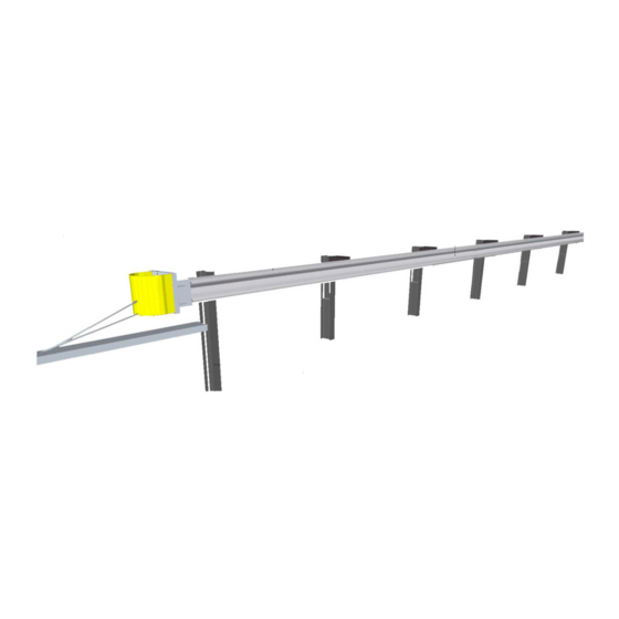
Page 3: System Overview
Level 3 system should take a two person crew less than two hours. The X-Tension Guardrail End Terminal is a highly engineered safety device made up of a rela- tively small number of parts. Before starting installation ensure that one is familiar with the make up of the system. - Page 4 INSTALLATION AND MAINTENANCE MANUAL STANDARD LIMITED WARRANTY Lindsay Transportation Solutions, Inc. “LTS” ( formerly Barrier Systems ) has tested the impact performance of its barriers and crash cushion systems, and other highway safety hardware under controlled conditions, however, LTS does not represent nor warrant that the results of those controlled conditions would necessarily avoid injury to persons or property.
-
Page 5: Limitations And Warnings
X-Tension Introduction (continued) Limitations and Warnings The X-Tension Guardrail End Terminal has been rigorously tested and evaluated per the recommendations in the NCHRP 350 guidelines for terminals and crash cushions. The impact conditions recommended in NCHRP 350 are intended to address typical in–service collisions. - Page 6 INSTALLATION AND MAINTENANCE MANUAL X-Tension Parts Identification Impact Head Friction Plate Soil Anchor (1 Required) (1 Required) (1 Required) B061072 B061058 B061104 Slider Bracket + Angle Bar Cable Bracket Cable Assembly (1 Required Roadside – 2 Median) (1 Required) (2 Required)
- Page 7 X-TENSION SYSTEM ® X-Tension Parts Identification Post # 2 (1 Req.) Galv. Line Post (3-6) Post #1 Bottom Roadside can be CRT Timber (CRT Timber Posts allowed roadside) (1 Required) B061100 BSI-1012078-00 B061098 W-Beam Guardrail RWM02a Median Radius Rail 1 (12’-6”) Median Secondary Head (3 Required Roadside –...
-
Page 8: Preparation
See bill of materials for the particular application and parts identification sheet. Ensure that the area where the X-Tension is to be installed is flat enough so that the soil anchor will not protrude more than 100mm (4 in) from ground level, when measured with a straight line over a 1.5m (5 ft) cord. -
Page 9: X-Tension Tangent Installation
X-TENSION SYSTEM ® X-Tension - Tangent Installation Instructions Step 1 - Set Out The tangent terminal is essentially an 11.4m (38 ft) continuation of the standard guardrail run. Pull a string line out with the desired offset (0 -450mm : 0-1.5 ft) over the length of the system, in a straight flare (Figure 1). - Page 10 INSTALLATION AND MAINTENANCE MANUAL X-Tension - Tangent Installation Instructions Step 2 – Installing Posts 6- 2 Begin installing posts 2 – 6 at standard highway post spacing, 75” (1905mm) and post height, 28 1/4” (720mm) or 31 3/4” (805mm) depending on the height of the system being installed.
- Page 11 X-TENSION SYSTEM ® X-Tension - Tangent Installation Instructions Step 3 – Post 1, Ground Strut and Soil Anchor Place the roadside face of post 1 bottom anchor, 200mm (8 in) towards the roadway to compensate for the lack of blockout (Figure 4). Post 1 bottom, the Ground Strut and the Soil Anchor are then placed parallel to the string line at this roadside offset position.
- Page 12 INSTALLATION AND MAINTENANCE MANUAL X-Tension - Tangent Installation Instructions Step 5 – Hang Rail 2 and Shear Bolts Before installing rail 2, double check that the blockout is already bolted to post 3. Bolt rail 2 to the post and blockouts at posts 4 and 5 with the appropriate post bolt (Figure 8).
- Page 13 X-TENSION SYSTEM ® X-Tension - Tangent Installation Instructions Step 7 – Assemble Slider Panel onto Rail 1 Start by sitting rail 1 on a blockout or post so that it is raised off the ground as shown (Figure 12). Slide the Slider Panel onto the downstream end of rail at post 3 location (Figure 13) and bolt into place using 4 standard splice bolts, pushing the bolt through from the inside of the slider to the outside so that the nut is on the traffic face.
- Page 14 INSTALLATION AND MAINTENANCE MANUAL Step 9 – Attach Impact Head Place Impact Head on upstream end of rail 1 and attach using 8 standard splice bolts with nuts on traffic face (Figure 17). Hint: Place bottom two bolts first then use guardrail pin bar to lever head up snug onto rail.
- Page 15 X-TENSION SYSTEM ® Step 11 – Installing the Cables Install the Friction Plate in the top of the Impact Head, adjustment hole up. Take the cable closest to the road, pick up the downstream cable fitting and walk to the head, passing the cable through the bottom hole, through the Friction Plate (Figure 21) and out the backside of the Impact Head.
- Page 16 INSTALLATION AND MAINTENANCE MANUAL Step 13 – Tightening the Cables Only tighten the cables using the nuts at the Cable Bracket end (post 7) (Figure 25). Do not tighten the cable nuts at front of the Ground Anchor. Tighten the cables until they are taut, i.e. they rest in the backside of the W-beam and do not visibly sag between posts (Figure 26).
-
Page 17: X-Tension Flared Installation
The system should not be installed on parabolic curve. Ensure that the area where the X-Tension is to be installed is flat enough so that the anchor will not protrude more than 75 mm (3 in) [100 mm (4 in) max] above ground level, when measured with a straight line over a 1.5m (5 ft) cord. - Page 18 INSTALLATION AND MAINTENANCE MANUAL X-Tension - Flared Installation Instructions Step 1 - Set Out Pull a string line out with the desired offset (0 -1.2m; 0-4 ft) Note that the flare is a straight flare, over the length of the system (11.4m; 38 ft) The string line should be set to follow the roadside edge of the posts (Figure 29).
-
Page 19: X-Mas Median Installation
(Figure 32). Ensure that the area where the X-Tension is to be installed is flat enough so that the soil anchor will not protrude more than 100mm (4 in) [preferred 75 mm 3 in)] from ground level when measured with a straight line over a 1.5m (5 ft) cord. - Page 20 X-MAS - Median Installation Instructions Step 1 - Set Out The X -Tension Median Attenuator is essentially one Tangent X-Tension installed parallel to one side of the median barrier (Figure 33), with a small number of additional components and rail attached parallel with the other side of the barrier (Figure 34).
- Page 21 X-TENSION SYSTEM ® X-MAS - Median Installation Instructions Step 3 – Attach Secondary Impact Head Fit secondary head to main head by pushing sideways onto the main head as shown below (Figure 35), until the holes in the gussets line up. Fix into place with either the 25mm (1 in) pin and pin lynch, or 2 M24 x 50mm (1 in X 2 in) bolts as shown (Figure 36).
- Page 22 INSTALLATION AND MAINTENANCE MANUAL X-MAS - Median Installation Instructions Step 5 – Attach Slider Bracket to Backside Rail 2 Bolt the Slider Bracket to the upstream end of rail 2 (at post 3) using 4 standard splice bolts (Figure 39). The angle bar end should be closest to the Impact Head end (Figure 40). Remove the angle bar and 2 M20 X 25mm (3/4 in x 1 in) bolts.
- Page 23 X-TENSION SYSTEM ® X-MAS - Median Installation Instructions Step 7 – Hang Curved Backside Rail #1 Lift rail 1 with Slider Panel attached and push the slider end over rail 2. Bolt rail 1 and blockout to post 2 using supplied standard post bolt and 50x50mm (2 in x 2 in) washer on inside of post bolt notch on the backside of post 2 (Figure 43).
-
Page 24: Optional Nose Cover
INSTALLATION AND MAINTENANCE MANUAL X-MAS - Median Installation Instructions Step 8 – Attach Nosing Push nosing into place on the front of the impact head. Attach using the supplied nylon push rivets (Figure 47). Delineation to be attached to nosing, as per Local Authorities requirements. Figure 47. -
Page 25: Installation Checklist
Installed By Date Inspected By Date X-Tension Tangent and Flared Systems [System Length 11.4m (38ft)] Y/N NA • Rail is bolted at all posts except post 3. • Post 1, post bolt notches face impact head. Bolted to ground strut. -
Page 26: Traffic Face Impacts
Unbolt the splice bolts first. Then unbolt the post bolts and lower rails to ground. Step 3: Remove X-Tension Components All the X-Tension components are attached to the rails with standard splice bolts. Unbolt and re- move the components. Step 4: Remove Posts Undo the bolt at the bottom of Post 1 and pull out post. - Page 27 X-TENSION SYSTEM ® X-Tension Maintenance (Head on Impacts) Head on Impacts Key Repair Steps: 1. Remove the cables 2. Pull the rails back 3. Remove components from rails 4. Remove damaged posts 5. Assess damage 6. Reassemble Step 1: Remove Cables...
- Page 28 INSTALLATION AND MAINTENANCE MANUAL Lindsay Transportation Solutions Sales and Services, Inc (888) 800-3691 [U.S. toll free] or +1 (707) 374-6800...
- Page 29 X-TENSION SYSTEM ® Lindsay Transportation Solutions Sales and Services, Inc (888) 800-3691 [U.S. toll free] or +1 (707) 374-6800...
- Page 30 INSTALLATION AND MAINTENANCE MANUAL Lindsay Transportation Solutions Sales and Services, Inc (888) 800-3691 [U.S. toll free] or +1 (707) 374-6800...
- Page 31 X-TENSION SYSTEM ® Lindsay Transportation Solutions Sales and Services, Inc (888) 800-3691 [U.S. toll free] or +1 (707) 374-6800...
- Page 32 INSTALLATION AND MAINTENANCE MANUAL Lindsay Transportation Solutions Sales and Services, Inc (888) 800-3691 [U.S. toll free] or +1 (707) 374-6800...
- Page 33 X-TENSION SYSTEM ® Page Left Intentionally Blank Lindsay Transportation Solutions Sales and Services, Inc (888) 800-3691 [U.S. toll free] or +1 (707) 374-6800...
- Page 34 INSTALLATION AND MAINTENANCE MANUAL Page Left Intentionally Blank Lindsay Transportation Solutions Sales and Services, Inc (888) 800-3691 [U.S. toll free] or +1 (707) 374-6800...
- Page 35 X-TENSION SYSTEM ® Page Left Intentionally Blank Lindsay Transportation Solutions Sales and Services, Inc (888) 800-3691 [U.S. toll free] or +1 (707) 374-6800...
- Page 36 180 River Road • Rio Vista, CA 94571 • +1 707.374.6800 U.S. Toll Free: 888.800.3691 • www.barrriersystemsinc.com Installation manual details for the X-Tension System are subject to change without notice to reflect improvements and upgrades. Additional information is available from Lindsay Transportation Solutions Sales and Service © Lindsay Transportation Solutions...
Need help?
Do you have a question about the X-TENSION and is the answer not in the manual?
Questions and answers