Table of Contents
Advertisement
Available languages
Available languages
Quick Links
Advertisement
Table of Contents

Related Manuals for OPISYS USHR-0819L

Summary of Contents for OPISYS USHR-0819L
- Page 1 Users Guide & Installation Manual USHR-0819L...
- Page 2 - Content - 1. General Information 2. System Components 3. Installation 4. Trouble Shooting 5. Specification 6. Certificates 7. Memo This device complies with Part 15 of the FCC Rules. Operation is subject to the following conditions; This device complies with the Industry Canada license-exempt RSS standard(s). Operation is subject to the following conditions;...
-
Page 3: General Information
1. General Information 1.1. Precautions Reference : Direction/Information for the proper operation Cautions : Information for users to avoid malfunctions Warning : Instruction for users to avoid unexpected hazard 1.1.1 Do not drop the device - It may damage the product and its function 1.1.2 Do not place near magnetic material - It may cause of possible malfunction 1.1.3 Product is recommended to be used with original AC/DC adapter... - Page 4 1.2 . Features 1.2.1. Summary This device may be installed on residential area, office, warehouse etc. . Following is advantage of using in-building repeater system. Decrease dropped call rate II. Increase signal strength III. Improve Data / Voice quality IV. Prolong hand phone battery life V.
-
Page 5: System Components
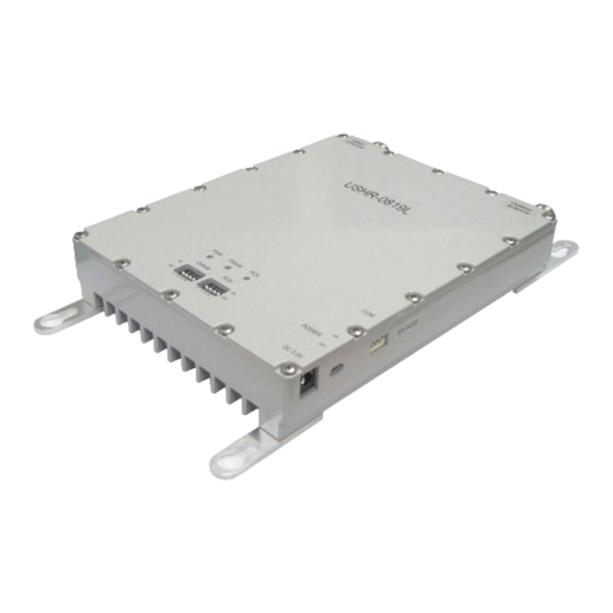
2. System components ② AC/DC Adapter ① Dual Band Repeater ④ Installation bolts ③ User Manual ① Dual band Repeater : BTS and mobile phone signal booster ② AC/DC Adaptor : 110V power supply ③ User Manual : Operation manual ④... -
Page 6: Installation
3. Installation 3.1. Installation diagram USHR-0819L 3.1.1. Install Donor Antenna on higher location to avoid any signal interference. 3.1.2. Install service antenna at appropriate location such as wall or roof ceiling. Make sure service antenna is not blocked by furniture or hope appliance. - Page 7 3.3. Repeater and Antenna connection 3.3.1. Connect donor antenna to RVS connector as shown below. 3.3.2. Connect Service antenna to FWD connector as shown below. 3.3.3. Plug in power adaptor to power outlet. Page 7...
- Page 8 3.3.4. Plug in AD/CD adaptor to connector listed as DC5.6V 3.3.5. Once power is on, it will show 3 green LED light on the front of product as shown below. Page 8...
-
Page 9: Troubleshooting
4. Trouble Shooting 4.1. LED Status Problem Item GREEN LED RED LED Reference See 4.1.1 See 4.1.2 See 4.1.3 Cellular See 4.1.4 See 4.1.5 See 4.1.6 See 4.1.7 See 4.1.8 4.1.1. Power on status 4.1.2. Power off status 4.1.3. Cellular normal operation condition 4.1.4. -
Page 10: Specification
5. Specification 5.1. Amplifier Specification Item Specifications Note Down Link 1930 ~ 1990 MHz PCS1900 BW: 60MHz Up Link 1850 ~ 1910 MHz Operating Frequency Down Link 869 ~ 894 MHz Cellular800 BW: 25 MHz Up Link 824 ~ 849 MHz Modulation Type GSM, EDGE, CDMA, WCDMA Input Power... - Page 11 4. 2. Mechanical Specification Item Specifications Note 151mm x 191mm x 35mm Dimensions (L W H) (5.95 x 7.5 x 1.38 inch) Weight 4. 3. Environment Specification Item Note Specifications Temperature -30 ~ 55℃(-22 ~ 131℉) Humidity 10 ~ 95% 4.
- Page 12 5. Certificates 5.1 FCC Certification Model : USHR-0819L ▪ Certificate Date : Oct. 2012 Q4EUSHR-0819L ▪ Certificate Number : 5.2 IC Certification Model : USHR-0819L ▪ Certificate Date : Oct. 2012 8605A-USHR0819L ▪ Certificate Number : Page 12...
- Page 13 6. Memo Page 13...
- Page 14 Guide de l'utilisateur & Manuel d’installation USHR-0819L...
- Page 15 - Table des matières - 1. Informations générales 2. Éléments du système inclus 3. Installation 4. Dépannage 5. Spécifications 6. Certificats 7. Mémo Cet appareil est conforme au paragraphe 15 de la règlementation FCC. Son fonctionnement est sujet aux conditions suivantes ; cet appareil est conforme à la licence Industry Canada-à...
-
Page 16: Informations Générales
1. Informations générales 1.1. Précautions Référence : Instruction/Information pour un fonctionnement correct ATTENTION : Information aux utilisateurs afin d’éviter tout mauvais fonctionnement Avertissement : Instruction aux utilisateurs afin d’éviter tout danger inattendu 1.1.1 Ne pas faire tomber l’appareil - Risque d’endommager l’appareil et son fonctionnement 1.1.2 Ne pas installer près de source magnétique - Risque possible de mauvais fonctionnement 1.1.3 Il est recommandé... - Page 17 1.2 . caractéristiques 1.2.1. Sommaire Cet appareil peut être installé dans des zones résidentielles, des bureaux, des entrepôts etc. . Voici une liste des avantages à se servir d’un Système de répéteur en intérieur. Baisse le taux d’appels déconnectés II. Renforce le signal III.
- Page 18 2. Éléments du système inclus ② Adaptateur AC/DC ① Répéteur double bande ④ Vis d’installation ③ Guide de l'utilisateur ① Répéteur double bande : amplificateur de signal BTS et téléphone portable ② Adaptateur AC/DC : fonctionne sur 110v ③ Guide de l'utilisateur : manuel d’utilisation ④...
- Page 19 3. Installation 3.1. Schéma d’installation USHR-0819L 3.1.1. Installer l’antenne extérieure sur un point élevé afin d’éviter toute interférence de signal. 3.1.2. Installer l’antenne de service à un endroit approprié, tel qu’un mur ou un plafond. S’assurer que l’antenne n’est pas bloquée par un meuble ou un appareil domestique.
- Page 20 3.3. Connexion du répéteur et de l’antenne 3.3.1. Connecter l’antenne extérieure au connecteur RVS tel qu'indiqué ci-dessous. 3.3.2. Connecter l’antenne de service au connecteur FWD tel qu'indiqué ci-dessous. 3.3.3. Brancher l’adaptateur sur une prise électrique. Page 7...
- Page 21 3.3.4. Brancher l’adaptateur AC/DC sur le connecteur référencé DC5.6V 3.3.5. Une fois branché, 3 LED vertes vont s’allumer sur la façade avant de l’appareil, tel qu'indiqué ci-dessous. Page 8...
-
Page 22: Dépannage
4. Dépannage 4.1. Statut LED Référence Élément LED VERTE LED ROUGE Problème Voir 4.1.1 Voir 4.1.2 Voir 4.1.3 Cellulaire Voir 4.1.4 Voir 4.1.5 Voir 4.1.6 Voir 4.1.7 Voir 4.1.8 4.1.1. État : allumé 4.1.2. État : éteint 4.1.3. Conditions normales de fonctionnement du cellulaire 4.1.4. -
Page 23: Spécifications
5. Spécifications 5.1. Spécifications de l’amplificateur Élément Spécifications Note Liaison desce 1930 ~ 1990 MHz ndante PCS1900 Liaison monta BW: 60MHz 1850 ~ 1910 MHz Fréquence de fon ctionnement Liaison desce 869 ~ 894 MHz ndante Cellular800 Liaison monta BW: 25 MHz 824 ~ 849 MHz Type de modulation GSM, EDGE, CDMA, WCDMA... - Page 24 4. 2. Spécifications de l’appareil Appareil Spécifications Note 151mm x 191mm x 35mm Dimensions (L l H) (5.95 x 7.5 x 1.38 inch) Poids 2 Kg 4. 3. Spécifications du milieu Élément Note Spécifications Température -30 ~ 55℃ (-22 ~ 131℉) Humidité...
- Page 25 5. Certificats 5.1 Certification FCC Modèle : USHR-0819L ▪ Date du Certificat : Oct. 2012 Q4EUSHR-0819L ▪ Numéro de Certificat : 5.2 Certification IC Modèle : USHR-0819L ▪ Date du Certificat : Oct. 2012 8605A-USHR0819L ▪ Numéro du Certificat :...
- Page 26 6. Mémo Page 13...
-
Page 27: Service Antenna Specification
Service Antenna Specification Model Name : PAT-CPWI-M ◆ Specification ◆ Photo Item Specification Frequency Range 824 ∼894 MHz 1750 ∼2400MHz VSWR ≥ 2.0 : 1 ≥ 1.5 : 1 Gain ≥ 4.0 dBi ≥ 7.0 dBi -3dB half power angle 90°±40°... -
Page 28: Donor Antenna Specification
Donor Antenna Specification Model Name : ALP-15QD-M ◆ Specification ◆ Photo Item Specification Frequency Range 824 ∼894 MHz 1750 ∼2400MHz VSWR ≥ 1.8 : 1 ≥ 1.5 : 1 Gain ≥ 5.0 dBi ≥ 11.0 dBi -3dB half power angle 80°...
Need help?
Do you have a question about the USHR-0819L and is the answer not in the manual?
Questions and answers