Table of Contents
Advertisement
Advertisement
Table of Contents

Related Manuals for Leaf True HDMI LHDMI66P


Summary of Contents for Leaf True HDMI LHDMI66P
- Page 1 LHDMI66P...
- Page 2 Do not connect any part of this equipment to Power Over Ethernet devices. Damage may result. During operation the Leaf LHDMI66 and associated LB1 breakouts may feel warm to the touch. This is quite normal. Please ensure that these items have sufficient cool air flow around them.
-
Page 3: Table Of Contents
Table of Contents INTRODUCING THE LEAF TRUE LHDMI66P ..........4 Overview ........................... 4 FRONT PANEL LAYOUT .................. 5 HDBase T Connections ....................5 Front Panel LED display and selection buttons ............5 REAR PANEL LAYOUT: ................6 RJ12 control port ......................7 4 way DIP switch module .................... -
Page 4: Introducing The Leaf True Lhdmi66P
The Leaf True HDMI Matrix LHDMI66P package comprises a Leaf LHDMI66 interface unit and six Leaf LB1 breakouts. It is designed to accept HDMI A/V sources at its inputs on the LHDMI66 and route them to remotely located LB1 breakouts. In this document, each input signal source is termed a source and each output and breakout is called a zone. -
Page 5: Front Panel Layout
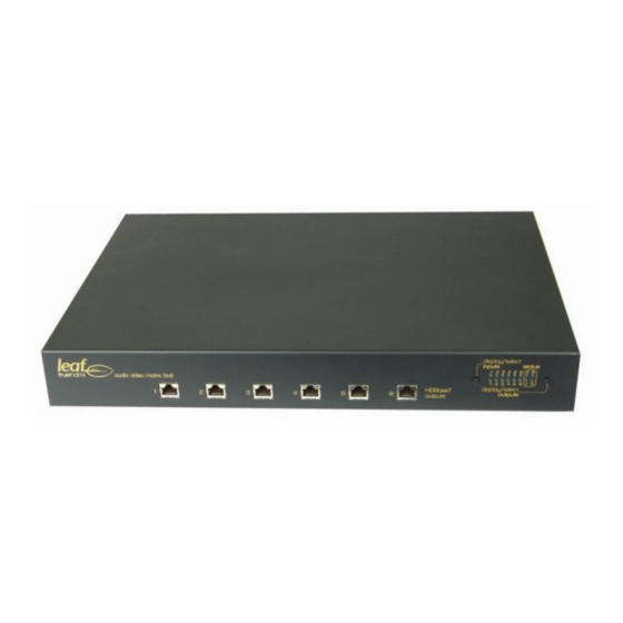
LHDMI66 front panel 1.2 HDBase T Connections Each Leaf True breakout is connected to the interface by way of a single Cat5e/6 cable to the HDBaseT output or zone ports on the front panel. 1.3 Front Panel LED display and selection buttons... -
Page 6: Rear Panel Layout
2 Rear panel layout: The LHDMI66 rear panel has the following fittings as depicted below. 1. 1 x RJ12 type Leaf Control input port 2. 1 x 4 way Dip Switch module 3. 6 x 3.5mm Tip Ring Sleeve sockets for connection of IR devices 4. -
Page 7: Rj12 Control Port
Zone 4. The IR ports support direct connection and drive of Leaf “hammerhead” and other compatible 5 volt, 3 wire (Tip Ring Sleeve / stereo plug) IR detectors to Leaf LB41 and other compatible 2 wire (mono plug) IR blasters. -
Page 8: Rs232 From Control System To Lb1 Breakouts
Leaf Serial Command documentation for further information. Connection from these ports to RS232 equipment would typically be achieved through the use of RJ45 to DB9 RS232 adaptor leads. Leaf Audio has suitable RJ45 to RS232 (DB9) Female adaptor leads (LT45DB9Female) available for sale. Male DB9 RS232 connection may require the additional of M-M gender bender(s). -
Page 9: Rs232 Serial Control Connectors
48h to4Dh 79 to 84 78 to 83 4Eh to 53h 85 to 90 84 to 89 54h to 59h 91 to 96 90 to 95 5Ah to 5Fh Table 2: BANK SELECT TABLE Leaf LHDMI66 manual Page 9 Of 19... -
Page 10: Rs232 Termination (Term) Switch
3D formats. 3 BREAKOUTS A Breakout is the “receiving end” of the Leaf True system and one is required for each connected “zone” of the Leaf True system. The LB1 is the breakout that is designed for use with LHDMI66. -
Page 11: Status Leds
This results in faster switching times and isolates the effect on one zone from another zone when new connections are routed. Refer to the Calibration description in the Operation section for more detail. Leaf LHDMI66 manual Page 11 Of 19... -
Page 12: Exclusive Source Selection (Zone Lock Mode)
When a global command is sent then the existing source is unlocked Locking a zone to a source that is already switched to one or more other zones will cause that source disconnect from those zones. Leaf LHDMI66 manual Page 12 Of 19... -
Page 13: Operation
1. Turn on all sources and zone equipment (receiver or TV). Ensure that zone equipment (TV’s etc) are set to the correct HDMI input. 2. Press and hold operated the left hand press button switch on the front panel for 3 seconds to commence calibration. Leaf LHDMI66 manual Page 13 Of 19... -
Page 14: Creating Input To Output Switched Selections
(source) is blue, then release the switch. The left hand six LEDs in the upper row indicate the input sources 1 to 6 left to right. (Source 1 is depicted in this picture) Leaf LHDMI66 manual Page 14 Of 19... -
Page 15: Clear All Switched Selections / Global Off
Standby mode will be indicated by the lower right hand LED (Status LED D) pulsing green / blue. Status LEDs A, B and C are reserved for future features. Leaf LHDMI66 manual Page 15 Of 19... -
Page 16: Interconnections
6 Interconnections 6.1 Interconnections at front panel 6.2 Possible interconnections at rear panel Leaf LHDMI66 manual Page 16 Of 19... -
Page 17: Possible Interconnections At Lb1
6.3 Possible interconnections at LB1 Leaf LHDMI66 manual Page 17 Of 19... - Page 18 Bank Select Switch POWER 45W 3.75A 12V DC. Consumption depends on resolution of distributed video and features enabled. 60W supply included – Use Leaf Audio supply only. DIMENSIONS (W, D, H) Approx 425mm x 290mm, x 55mm Leaf LHDMI66 manual...
- Page 19 Connect the equipment into an outlet on a circuit different from that to which the receiver is connected. Consult the dealer or an experienced radio/TV technician for help. Modifications not expressly approved by the manufacturer could void the user's authority to operated the equipment under FCC rules. Leaf LHDMI66 manual Page 19 Of 19...
Need help?
Do you have a question about the True HDMI LHDMI66P and is the answer not in the manual?
Questions and answers