Table of Contents
Advertisement
Quick Links
M
O
IXER
VERVIEW
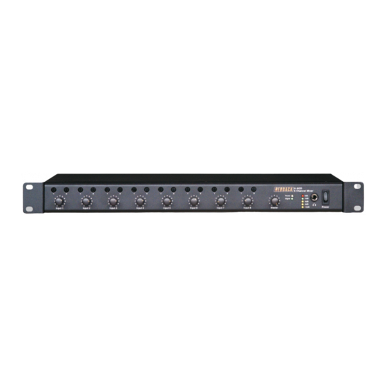
Description
This Redback
®
8 channel mixer has been designed to
meet the requirements of professional public address
installations. Its many features makes it ideally suited for
use in shopping centres, gymnasiums, places of worship,
office complexes, board rooms, council chambers, court
rooms etc.
Inputs and Outputs
Inputs 1-6 can be configured for balanced microphone or
line use as desired. XLR and dual RCA sockets are
provided for each of these inputs. Inputs 7 & 8 are
dedicated line inputs provided with dual RCA sockets and
variable muting/ducking level. Outputs are 600Ω/0dBm
XLR balanced or dual RCA sockets for record/tape out.
Input Configuration
Inputs 1-6 include an individual 4 way dip switch enabling
selection of mic or line input operation, adjustable line
input sensitivity (100mV or 1V), mic or line operation of
priority/VOX muting (see below for priority details) and
phantom power on/off.
A DIP switch is provided for inputs 7 & 8 enabling the
adjustment of the input sensitivity (100mV or 1V).
Front Panel Controls
The front panel includes individual volume controls and
tamper proof, screw driver adjust, treble and bass
controls for each input channel. A LED VU meter and a
headphone socket are provided.
Priority and Muting
The mixer incorporates three levels of priority. Inputs 1,2
and 3 will operate the priority/VOX muting regardless of
the input configuration ie: both microphone and line
inputs will operate the priority/VOX circuit if this
function is selected ON for that input. This is
particularly useful when an input is set for line use, as it
enables telephone paging, radio microphone, emergency
tones, jukebox or similar to mute background music on
other inputs.
Three level priority operates as shown:
Input 1 Priority 1 – mutes inputs 2 - 8,
Input 2 Priority 2 – mutes inputs 3 – 8,
A 4425
®
Public Address Mixer
Operating Instructions
Input 3 Priority 3 – mutes inputs 4 – 8,
Inputs 4-8 are mixed. If the priority function for inputs 1-3
is turned off, then inputs assume no priority and its output
will be mixed with inputs 4-8 ie. if all priority functions are
switched OFF then all inputs will be mixed.
When fitted the optional A 2073 assumes priority 2.
Adjusting VOX muting sensitivity
The adjustment pots are located internally. See page 2
for diagram.
1. Switch off the unit and remove the 240V mains lead
and 24V in from the rear.
2. Remove the 6 x M3 screws from the lid and remove
the lid.
3. The adjustment pots are located on the main (middle)
PCB and are marked EVAC, MIC1, MIC2, MIC3.
Adjust the appropriate pot clockwise to increase
sensitivity and anti-clockwise to decrease sensitivity.
4. Replace lid and screws and reapply power.
Optional Modules
Alert and evacuation tones are available with the
installation of the optional A 2073 tone generator.
An optional compressor/compander module (A 4426) can
be fitted internally to inputs 7 and 8. This is desirable
when using CD/DVD players as a BGM source. It
maintains a consistent output level during CD/DVD
playback to eliminate constant adjustment of volume
levels from quiet tracks to louder tracks on the disc.
Switch
1
2
3
4
Switch
1
2
3
4
www.altronics.com.au
TABLE 1: DIP SWITCH SETTINGS
Inputs 1 - 6 (refer to DIP 1-6)
Item
On
Input Type
Line
Line Level
1V
Priority
On
Phan. Pwr
On
Inputs 7 - 8 (refer to DIP 7)
Item
On
Input 8
1V
-
-
-
-
Input 7
1V
Off
Mic
100mV
Off
Off
Off
100mV
-
-
100mV
Advertisement
Table of Contents

Related Manuals for Redback A 4425


Summary of Contents for Redback A 4425
- Page 1 A 4425 ® Public Address Mixer Operating Instructions Input 3 Priority 3 – mutes inputs 4 – 8, IXER VERVIEW Inputs 4-8 are mixed. If the priority function for inputs 1-3 Description is turned off, then inputs assume no priority and its output This Redback ®...
- Page 2 REDBACK A 4425 Mixer NSTRUCTIONS For the best sound performance turn the input level Remove the mixer from its packaging and inspect for any control to a high setting (say 3/4 ) and use the Master as damage. If the unit appears to be damaged then do not the volume control.
- Page 3 Output Tape 24V DC Input 7/8 Mute Level 240V AC A 4425 Rear Panel Layout ROUBLE HOOTING Fault/Symptom: No Sound Fault/Symptom: Microphone Does Not Work • Check that there is power on both the mixer and power • The microphone may need phantom power. If so set the amplifier.
- Page 4 REDBACK A 4425 Mixer PECIFICATIONS INPUT CONNECTORS Inputs:......6 microphone - balanced 200-600Ω Mic inputs: ..........3 pin XLR balanced 2 line - unbalanced 100kΩ Line inputs: ..........Dual RCA sockets Output: ..........600Ω balanced 0dBm CONTROLS DISTORTION Mic inputs: ..............Volume Mic inputs:............< 0.3% @ 1KHz Line inputs:..............Volume...
Need help?
Do you have a question about the A 4425 and is the answer not in the manual?
Questions and answers