
Subscribe to Our Youtube Channel
Related Manuals for Clearfield YOURx Flex Box

Summary of Contents for Clearfield YOURx Flex Box
- Page 1 YOURx Flex Box Installation Manual ______________________________________________________ Manual 019209 REV F - Jan 2019...
-
Page 2: Table Of Contents
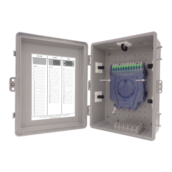
YOURx Flex Box Installation Manual _________________________________________________________ Table of Contents Recommended Tools Parts List Components: Aggregator Plates Ship along Items Using the Flex Box with Drop Wheels (Max 16) Using the Flex Box Clearview Blue Cassette (Up to 24 ports) Using the Aggregator Plates... - Page 3 Description The YOURx Flex Box is a secure, modular wall box with slide-in aggregator plate that supports multiple cable entries like, individual fiber cables, conduit and microduct in an organized matter. Installers simply push the microduct into the aggrega- tor plate and they are ready to pull fiber.
-
Page 4: Recommended Tools
YOURx Flex Box Installation Manual _________________________________________________________ Recommended Tools Find No. Tool Image Rotary Cutter Flat Cutter Deburring Tool Phillips Screwdriver Pliers Optical End Face Cleaning kit Direct: 763.476.6866 • National: 800.422.2537 • www.SeeClearfield.com • techsupport@clfd.net Manual 019209 REV F - Jan 2019... -
Page 5: Parts List
YOURx Flex Box Installation Manual __________________________________________________________ Parts List Flex Box Ground Post Screw Hook Dimensions: 16”H X 12”W X 5.38”D Port Density: Two Cassettes (24 ports) or up to 16 drop wheels Notes: • Mounting hardware NOT included • Bond/ground per local practices... -
Page 6: Components: Aggregator Plates
YOURx Flex Box Installation Manual _________________________________________________________ Components: Aggregator Plates Slide-in aggregator plates support multiple cable entries (individual fiber cables, conduit and microduct) in an organized manner. Technicians can simply snap off a tab to a FlexPort, debur, and push in microduct. Then they are ready to pull fiber. -
Page 7: Ship Along Items
YOURx Flex Box Installation Manual __________________________________________________________ Ship along Items Qty (5) Adhesive backed Fiber Management blocks w/Velcro Qty (4) Fiber management radius limiters with mounting screws Qty (2) Threaded rod with nylon nuts Direct: 763.476.6866 • National: 800.422.2537 • www.SeeClearfield.com • techsupport@clfd.net... - Page 8 Installation Manual _________________________________________________________ The YOURx Flex Box is modular in design which can be configured in the following ways: With the use of up to 2 Cassettes (24-ports) (Figure 1) The drop wheel feature, which accommodates up to 16 individual drop wheel assemblies with each drop wheel supporting up to 200ft of FieldShield StrongFiber storage.
-
Page 9: Using The Flex Box With Drop Wheels (Max 16)
YOURx Flex Box Installation Manual __________________________________________________________ Using the Flex Box with Drop Wheels (Max 16) Secure the drop wheel cradles with the provided screws following the provided hole diagram. NOTE: In earthquake regions,the drop wheel cradle requires three screws per side. - Page 10 YOURx Flex Box Installation Manual _________________________________________________________ Drop wheels easily deploy by extending the wheel from the mounting cradle, pulling the fiber through the microduct, and then assembling the pulled connector. Characteristic Specification Material Black Thermoplastic Fiber 200 Feet of FieldShield StrongFiber...
- Page 11 YOURx Flex Box Installation Manual __________________________________________________________ 5. Assemble the connector, following instructions on the package or the steps below: Housing Assembly Step 1: Remove the white protective dust cap from the unassembled connector (Figure 1). Note: The SC Pushable Connector has a keyed locking feature that holds the inner housing to the connector and aligns the ferrule when the two are correctly mated.
- Page 12 YOURx Flex Box Installation Manual _________________________________________________________ Additional Slack 6. At the Drop Wheel, route the standard Storage connector from the center of the Drop Wheel through the access slot on the side of the Drop Wheel to the appropriate port on Drop Wheel (Figure 7).
-
Page 13: Using The Flex Box Clearview Blue Cassette (Up To 24 Ports)
YOURx Flex Box Installation Manual __________________________________________________________ Using the Flex Box Clearview Blue Cassette (Up to 24 ports) Fiber management is provided for both incoming and outgoing fiber in separate areas to reduce service interruptions when turning up additional subscribers. Place all 4 of the fiber management radius limiters onto the Flex Box, in the designated holes as shown in (Figure 1). - Page 14 YOURx Flex Box Installation Manual _________________________________________________________ 3. Place the two threaded rods (screw in) into pems, located in base of wall box. (Figure 3) 4. Slide cassettes onto threaded rods, utilizing the holes in side rail of cassettes and place nylon nuts to secure.
- Page 15 YOURx Flex Box Installation Manual __________________________________________________________ 1. Place screw hook into a convenient location (hole) for tying off pullstring when waiting to pull fiber (Figure 6). 2. Flex Box is now ready to accept fiber (Figure 7). Note: Cassette can be mounted in either direction.
-
Page 16: Using The Aggregator Plates
9 10 11 12 black “X”, indicating that the port has a FlexPort installed to accept microduct. Clearfield recommends the following port assignment. Working from back (bottom in Figure 3): Figure 3 1-6, then moving up to next row 7-12…etc. -
Page 17: Using The Combo Aggregator Plates
YOURx Flex Box Installation Manual __________________________________________________________ Using the COMBO Aggregator Plates COMBO Plate (Figure 1) with (24) 10/6mm ports. Also has the ability to have field installed FlexPort, sealcons or conduit fittings. Note: Max hole size is 2 3/8” (to keep integrity of the plate intact). -
Page 18: Installing Microduct Into Aggregator Plate
YOURx Flex Box Installation Manual _________________________________________________________ Installing Microduct into Aggregator Plate 1. Using a pair of pliers, snap off tab of desired FlexPort (marked with black “X”). (Figure 1) 2. De-burr port, using the de-burring tool as shown, or snips/knife, to remove any sharp edges. -
Page 19: Installing Additional Flexports
YOURx Flex Box Installation Manual __________________________________________________________ 10/6mm 14/10mm Installing Additional FlexPorts FlexPort Fitting FlexPort Fitting O-Ring FlexPorts are factory installed into aggregator plates that Green Spacer come from the factory based on the port count specified at time of order. - Page 20 YOURx Flex Box Installation Manual _________________________________________________________ DROP CABLE OPTIONS Product Cable FieldShield Jacket Can be Best Temperature Name Jacket Connector Color stapled Application FieldShield FLATdrop For use when fast installation Outdoor -40° to 176°F Black and low up-front cost is most desired feature.
-
Page 21: Connector Cleaning Procedure
Figure 1 These are Clearfield recommended products/application. Use the product you feel will complete your cleaning procedures. Create a “best practice” for your company and follow those procedures. - Page 22 YOURx Flex Box Installation Manual _________________________________________________________ • CLEAN THE FERRULE…Lightly moisten the fiber optic swab (2.5mm/38542F or 1.25mm/38040) by spotting a small amount (about 1”) of Electro-Wash PX or Electro-Wash MX pen onto the QBE-2. Hold the swab, 1 side down to the wetted area and hold for a count of 1-2-3-4-5.
- Page 23 YOURx Flex Box Installation Manual __________________________________________________________ Cleaning an MPO/MTP Connector Female Connector • Place one wiping paper on QbE-2 FiberSafe™ Cleaning Platen and apply small amount of precision cleaner (about 1” in diameter) with Elec- tro-Wash MX pen on to one end of the wipe. Figure 1 •...
-
Page 24: Standard Warranty
Clearfield shall repair or replace the defective Product at its sole option and discretion, and return the repaired or replacement Product to Cus- tomer’s site, freight prepaid. Note: If the Product is not found to be defective by Clearfield, the product will be returned to the Customer and the customer billed for freight in both directions. -
Page 25: Proprietary Notice
__________________________________________________________ Proprietary Notice Information contained in this document is copyrighted by Clearfield, Inc. and may not be duplicated in full or part by any person without prior written approval of Clearfield, Inc. Its purpose is to provide the user with adequately detailed documentation to efficiently install the equipment supplied. Every effort has been made to keep the information contained in this document current and accurate as of the date of publication or revision.
Need help?
Do you have a question about the YOURx Flex Box and is the answer not in the manual?
Questions and answers