Table of Contents
Advertisement
Quick Links
Advertisement
Table of Contents

Summary of Contents for Condux Gulfstream 350e
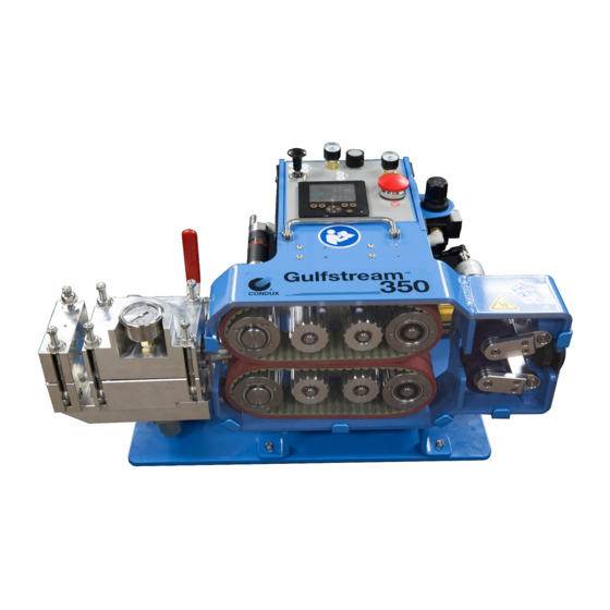
- Page 1 USER'S GUIDE & SAFETY MANUAL Gulfstream™ 350e...
- Page 4 For any information related to the machine (use, maintenance, spare parts) always state Model, Serial Number, and Manufacturing Year. This data can be found in the machine identification table. Manufacturer: Condux International Inc. 145 Kingswood Drive Mankato, MN United States 56001...
-
Page 5: Table Of Contents
Table of Contents General Information ..................6-7 Technical Information . -
Page 6: General Information
GENERAL INFORMATION The operating instructions contain a full description of the Gulfstream™ 350e, which has been designed for the purpose of feeding fiber optic cable through round conduits of uniform cross section. The conduit must previously have been installed underground or overhead to receive the fiber optic cable and must be of sufficient length on exit to be received by the machine. The conduit must be made from HDPE material to be adequately sealed in the exit of a machine. The conduit must be air tight up to a pressure of 215 psi (15 bar). For this purpose, connectors of screw, compression or fusion type must be used. Conduits from (8 mm) to 1.25" (42 mm) and fiber optic cables from 5/32" (4 mm) to 5/8" (16 mm) diameter can be accepted by the machine. TRADITIONAL DUCT Fiber optic cable is fed into the conduit by combining pulling and pushing forces, which draw the fiber optic cable through the conduit. The pulling force is achieved by... - Page 7 Machine must only be used for the work it was designed for. c. Machine is not to be used by unauthorized personnel in any application. d. Should there be any doubt concerning use, maintenance or anything else, please contact the factory or authorized Condux Supplier. OPERATOR QUALIFICATIONS a. Operator in charge of the machine and installation project must be appropriately dressed, avoiding loose clothes, hanging jewelry or whatever might become entangled in the moving parts.
-
Page 8: Technical Information
TECHNICAL INFORMATION A. CONDITION OF USE Temperature from 21° F ( -6° C) to 110° F (+43° C)Humidity from 30% to 90% +/- 5% Weather conditions relevant to working conditionsNatural and/or artificial lighting of the work site, minimum 200 lux B. AIR COMPRESSOR REQUIREMENTS • Pneumatic Pressure: 215 psi (15 bar) Maximum • Required Flow Capacity: 35 SCFM(1 m3/min) to 375 SCFM (11 m3/min) •... -
Page 9: Safe Operating Procedures
TECHNICAL INFORMATION & SAFE OPERATING PROCEDURES H. CONDUIT COUPLING REQUIREMENTS (CONTINUED) • Conduit ends must be cut off squarely and deburred. • Conduit must be fully seated into the coupler. • Couplers should be installed in a straight section of conduit. • Must be same size as conduit. Read and understand all procedures and safety instructions before using the Gulfstream™ 350e. Observe all safety information on this page and note specific safety requirements as explained by procedures called out in this manual. Failure to follow these instructions could result in serious personal injury, property damage or death. A. -
Page 10: Unpacking The Gulfstream™ 350E
• Fiber Guides 4-8 mm, 8-12 mm, 12-16 mm • 9/16 Stubby Ratchet Wrench (14.288 mm) • 5⁄8 " x 600 lb. Swivel (15.875 mm) • Venturi Air Plug • Plastic Divided Case w/Parts Label, Capscrew Set (10x) (M04-0.7’s) • BSP to NPT Pipe Fitting • Double Lock Claw Fitting • Machine Screw Kit • Allen Wrench (3⁄32") (2.681 mm) • Allen Wrench (2.5 mm) • Replacement Seal Kit NOTE: If any parts are missing: please contact your Condux representative or call Condux International at 1-800-533-2077 (USA or CANADA), or 1-507-387-6576. Figure 2. Unpacking the Figure 3. Common Parts Kit Gulfstream™ 350e... -
Page 11: Set Up The Blower
SET UP THE BLOWER This manual contains setup and operating instructions for the Gulfstream™ 350e. IMPORTANT: The Gulfstream™ 350e must not be located below overhead gantries, power lines or walkways where there might be a risk of falling objects. The operator must be wearing recommended protective gear before operating the blower (See page 9). Operating light levels should be at least 200 lux of light intensity. IMPORTANT: The Gulfstream™ 350e should not be positioned on a slope in excess of 13°. Remove the Gulfstream™ 350e from the storage box using the handle provided on the top of the machine (Figure 4). -
Page 12: Set Up For E Recording
SET UP FOR E RECORDING A. CONNECT 3 PIN CORD SUPPLIED TO BATTERY CLIP AND TO THE MACHINE. B. CONNECT 8 PIN CORD TO CONTROL BOX AND MACHINE. 1. Battery charger and battery not included Battery (Dewalt DCB205) or equivalent 20V Charger (Dewalt DCB101) or equivalent C. INSERT BATTERY D. ONCE POWERED UP 1. - Page 13 Figure 9. E Recording Figure 10. E Recording Duct Duct Back Button 6. Select Duct (Figure 9) 7. Fill out info as complete as you can 8. Select Back Arrow (Figure 10) 9. Select Cable (Figure 11) 10. Fill out info as complete as you can 11.
- Page 14 12. Select Blowing Machine/Compressor (Figure 13) 13. Fill out info as complete as you can 14. Select Back Arrow (Figure 14) 15. Select Crash (Figure 15) 16. This will be the screen you see. When you do the crash test have this screen up and record the Current Pressure readings (Figure 16-1).
- Page 15 18. Select Home. You should be back at this screen. (Figure 17) 19. Select off to turn recording on. This is what you should see (Figure 17) 20. Start Blowing 21. While blowing you can monitor each parameter by touching the name. Example: Speed, Air Block, Clamp Force, Push Force. Or monitor all by selecting the middle graph button (Figure 18) 22. When finished blowing hit P, then hit Cable, enter the Cable Mark END. Then go to home and hit OFF to stop recording. Hit P and note the ID for reference to the report information (Figure 19).
-
Page 16: Download To Usb With No Tablet
DOWNLOAD TO USB WITH NO TABLET A. DOWNLOADING PULL INFORMATION TO USB 1. Select P (Figure 20) 2. Select USB (Figure 21) 3. Insert USB on side of box (Figure 22) 4. Hit Copy to USB (Figure 23) 5. Then hit the Home Icon (Figure 23) Figure 20. - Page 17 Figure 22. Insert USB Figure 23. Copy to USB...
-
Page 18: Download With Tablet
DOWNLOAD WITH TABLET A. DOWNDLOAD PULL INFORMATION WITH A TABLET 1. Connect tablet to the control box: a. Go to Settings (Figure 24) b. Go to WIFI (Figure 25) c. Turn WIFI on (Figure 26) d. Select GS 350 (Figure 27) Figure 24. Select Settings Figure 25. - Page 19 Figure 26. WIFI On Figure 27. Select GS350 e. Enter password: Condux145 (passwords are case sensitive) f. Connect...
- Page 20 2. Go to home page and select the Condux Installation Report App (Figure 28) Figure 28. Open Installation Report App a. Select the CONNECT/REFRESH tab (Figure 29) Figure 29. Run the Installation Report...
- Page 21 3. To view or modify blowing parameters: a. Click on the image of the GS350 (Figure 29) b. This will open a tab to view the graphs. User is able to view and modify parameters if needed (Figure 30). Figure 30. Graph Parameters...
- Page 22 4. Select information to download: a. Select Date of Run you want to download (Figure 31) Figure 31. Select Date of Run b. Then select the Job ID you want (Figure 32) c. This will load all data and a graph Figure 32. Select Job ID...
- Page 23 d. Hit GENERATE REPORT (Figure 33) Figure 33. Generate Report e. Then you will see this on the screen (Figure 34) Figure 34. Generate Report...
- Page 24 f. Go to the home page and select My Files (Figure 35) Figure 35. My Files g. Select Internal Storage (Figure 36) Figure 36. Internal Storage...
- Page 25 h. Select Reports folder (Figure 37) Figure 37. Reports Folder i. Select Report, hold down until you get a check mark, go to the top and select share and email (Figure 38) Figure 38. Reports Folder...
-
Page 26: Cable Crash Test
CABLE CRASH TEST Cable Crash Testing is a very quick and easy step to be completed before attempting the installation of cable with the Gulfstream™ 350e. This test is necessary to set the air motor pressure of the blower below the point that it may cause cable damage as a result of over pushing or encountering an obstruction in the sub-duct system. It is also a necessary step to set the proper clamp force on the cable so there is no damage caused by slippage of the tractor drive at the desired air motor pressure. - Page 27 4. Cut a piece of fiber optic cable 15' (5 m)long. This is your test piece of cable. 5. Install the correct size Venturi to fit the cable being installed (Figure 41). Figure 41. Install Venturi 6. Attach the Air Hose. The Gulfstream™ 350e’s air system uses a Universal Claw fitting (US)(Figure 61). Take caution in routing the hose to prevent a tripping hazard. Follow these steps to connect the air hose: A. Attach the Universal claw fitting to the compressor to the machine (Figure 42). Make sure valve is in off or exhaust position (Figure 43). Figure 42. Attach Claw Fitting Figure 43. Air Valve B. Start the compressor and check all connections for leaks . In cold weather, run compressor until it is warmed up. Observe the following precautions to avoid pnuematic hazards: • Tighten all connections before applying pressure. Relieve pressure before connecting or disconnecting hose. • Do not exceed working pressure of pneumatic hose (not supplied). Visually inspect hose regularly and replace if damaged.
- Page 28 7. Feed fiber through the machine, seals, and venturi into the duct (Figure 44). 8. Feed fiber through machine and mark the fiber at the back end of the Gulfstream™ 350e (Figure 45). Figure 45. Mark the Fiber Figure 44. Run the Fiber 9. Pull 10' (3 m) of fiber back out of the duct (Figure 46). 10. Set the motor speed regulator and clamp force regulator. With small fiber, start at 20psi (Figure 47 & 49). Figure 47. Motor Speed Regulator Figure 46. Pull Back Fiber 11. Belts should be in the open position and needle valve should be off (Figure 64). 12. Lower the belts to engage the fiber. Turn air on and engage belts, which will start the belts. Fiber should be installing (Figure 48).
- Page 29 Figure 48. Lower Belts 13. Repeat crash test until fiber doesn't slip and max force is achieved. A. If fiber slips, pull back and increase the clamp force (Figure 49). B. If fiber comes off the belt drive or folds past mark at back end, decrease the motor force (Figure 50). Figure 50. Motor Speed Regulator Figure 49. Clamp Force Regulator C. If fiber stops and you are satisfied, mark down both the motor psi (or Bar) and clamp force psi (or Bar). Do not exceed these pressures during your install, as fiber integrity will be compromised. 14. Proceed to Pressure Test.
-
Page 30: Pressure Test Conduit
PRESSURE TEST CONDUIT The conduit system must be able to withstand a maximum pressure of 215 psi (15 Bar), and be free of leaks. Pressure test products are available to perform this test. These tests are sold seperately. Conduit may also be tested using the Gulfstream™ 350e. Follow the steps below: 1. - Page 31 5. Choose the correct Venturi to fit the cable being installed. Do not install at this time! 6. Clamp conduit in place (Figure 55). Figure 55. Clamp Conduit 7. Place Seal Disk in Venturi slot (Figure 56). 8. Close Air Block Cover and secure (Figure 57). Tighten nuts securely, but do not overtighten (SNUG). Use a cross-tightening procedure. Figure 56. Place Sealing Disk Figure 57. Close Air Block...
- Page 32 GULFSTREAM™ 350 CABLE PACKS & DUCT PACKS Gulfstream 350 Cable Packs ™ Part Number Description Part Number Description Part Number Description 08781162 8.1mm - 12.0mm Cable Pack 08781160 4.0mm - 4.5mm Cable Pack 08781164 15.6mm - 16.5mm Cable Pack 08780969K Cable Seal Kit (8.5mm) 08780960K Cable Seal Kit (4.0mm) 08780984K Cable Seal Kit (16.0mm) 08780970K...
- Page 33 GULFSTREAM™ 350 DUCT PACKS Gulfstream 350 Duct Packs (continued) ™ Duct Pack Duct Clamp Duct Seal Carrier Foam Carrier Cable Grip Innerduct Eye Duct Duct Carrier Carrier Duct Part Number Pack Duct Pack Part Part Part Part Part Duct Size and ID Range Part Number Number...
- Page 34 9. Plug receiving end of Conduit with a suitable sized Conduit Pulling Eye or micro duct end stop (Figure 58). 10. Choose the correct Pulling Grip & install on receiving end of Conduit over pulling eye or end cap (Figure 59). Figure 59.
- Page 35 12. Slowly open Ball Valve (Figure 62). Pressurize conduit to 80-100 psi (5.5-6.9 bar). and open Needle Valve (Figure 63). Figure 62. Ball Valve in Figure 63. Needle Valve to control Open Position air into the duct 13. Prove conduit integrity. a. Close Needle Valve (Figure 63). b. Conduit must not lose more than 20 psi (1.38 bar) over a 2-minute period. c. After 2 minutes, relieve air pressure. Open ball valve by moving the blower ball valve handle counter clockwise to the 3 o'clock position.
-
Page 36: Prepare Conduit For Proof & Prepare Conduit For Install
PREPARE CONDUIT PROOF & PREPARE CONDUIT FOR INSTALL 1. Remove Pulling Grip and then remove Conduit Pulling Eye or End Stop from exiting end of Conduit. After removing pulling eye or end stop, re-install pulling grip in order to catch Foam Carrier during conduit lubrication (Figure 64). 2. Open the Air Block Cover (Figure 65). Figure 64. Install Pulling Grip Figure 65. Air Block Cover 3. Pour recommended (silicon-based) lubricant into Conduit opening before Foam Carrier: 1 quart/6000 feet (1 liter/2 km) (Figure 66). (See Page 37 for lubricant chart) 4. Foam Carrier comes with Traditional Duct Packs. Micro Ducts you will need a pressure and proofing kit. Insert Foam Carrier (selected according to conduit size) into Conduit (Figure 67). - Page 37 LUBRICANT CHART TRADITIONAL DUCT SIZE LUBRICANT AMOUNT Lubricant Quantity per Lubricant Quantity Duct Size 1000 feet per Kilometer 1 in/2.5 cm 3 fl oz 300 ml 1.25 in/3 cm 4 fl oz 400 ml 1.5 in/4cm 5 fl oz 500 ml 2 in/5 cm 6 fl oz 600 ml...
- Page 38 6. Close the Air Block Cover. Tighten nuts securely, but do not over tighten (Figure 68). Use cross tightening procedure with the rachet to secure completely. Figure 68. Close Air Block Figure 69. Connect Air 7. Spread lubricant through Conduit. a. Re-connect the air hose to the fiber blower and attach all safety clips (Figure 69). b. Turn the Ball Valve handle to the 9 o’clock position and turn on the air from the compressor (Figure 62). c. Slowly open Ball Valve by turning to the 9 o’clock position. d. Make sure Needle Valve is open (Figure 70). e. Blow Foam Carrier through conduit to spread lubricant and check for blockage. Follow all safety precautions. f. After the Foam Carrier exits, close Ball Valve. NOTE: Foam Carrier must exit in a reasonable time, allow for approximately 10 seconds per 1,000 feet (300 m) for traditional duct. If longer than 10 seconds duct may be contaminated or blocked.
- Page 39 8. Ensure Air Block is depressurized. Open Ball Valve by moving the blower ball valve handle counter clockwise to the 3 o’clock position (Figure 71). Shut off the air from the compressor, decompress the air in the hose and disconnect the hose from the blower. 9. Remove Seal Disk (Figure 72). Figure 72. Remove Seal Disk Figure 71. Depressurize Air Block 10. Install Venturi (Figure 73). NOTE: The venturi with the hole goes into the bottom of the air block and gets screwed into place, while the top half sets on top of the bottom half (Figure 73). Figure 73. Install Venturi...
-
Page 40: Prepare Cable For Traditional Duct
PREPARE CABLE FOR TRADITIONAL DUCT The Gulfstream™ 350e is designed so cable may be installed into the machine from the side. Follow these steps so cable is properly positioned to begin operation. 1. Choose the correct Cable Grip and install on fiber optic cable (Figure 74). 2. Install 5/8" (16 mm) Swivel on Cable Grip. Grip must be firmly secured to cable (Figure 75). Note: The eye on the grip can be compressed to fit smaller diameter conduits. The eye of a new grip can be taped with electrical tape in order to make it narrower and travel more easily through the conduit. - Page 41 Figure 78. Add Lubricant Figure 79. Feed Carrier Assembly into duct. Figure 80. Install Cable into Blower 5. Add silicone lubricant (PL5000) for micro duct and (PL2000) for traditional duct into Conduit before Carrier: 1/2 quart/6000 feet (.5 liter/2 km) (Figure 78). (See Page 37 for lubricant chart) 6. Push Carrier, Swivel and Grip into Conduit (Figure 79). 7.
- Page 42 Figure 81. Add Lubricant Figure 82. Choose Cable Seals 8. Add lubricant to Conduit behind Cable Assembly: 1/2 quart/6000 feet (.5 liter/1 km) (Figure 81). 9. Choose the correct Cable Seals and install on cable. Cone side of Cable Seal faces conduit. Place Cable Seals into Venturi, split side down (Figure 82).
-
Page 43: Prepare Cable For Micro Duct
PREPARE CABLE FOR MICRO DUCT 1. Install optional cable tips onto end of fiber to be installed (Figure 84). 2. Feed cable through counter rollers and tractor drive belts. Reinstall cable guides (Figure 85). 3. Choose the correct cable seals and install on cable. Cone side of cable seal faces conduit. Place cable seals into venturi grooves, split side down (Figure 86). 4. Close air block cover. Tighten nuts securely, but do not over-tighten. Use cross tightening procesure to completely secure (Figure 87). -
Page 44: Blower Operating Instructions
BLOWER OPERATING INSTRUCTIONS A. FINAL INSPECTION Before placing the blower into operation, always perform a final inspection of all components used. B. OBSERVER AT EXIT PIT Station an observer with a 2-way communication device, at the far end of the Conduit, where the Cable carrier will exit. C. NOTIFY crew that preparations are complete and cable blowing is to begin. IMPORTANT: It is recommended that if a reel-tensioning unit is not being used, the cable reel should then be kept under control by a second operator who is required to wear proper safety equipment and maintain a proper distance from the cable (See page Figure 88. - Page 45 5. For Traditional Duct, slowly rotate the motor speed regulator knob counter clockwise (Figure 51 page 29) to engage tractor drive and increase speed. Push 50 to 100 Feet (15 m to 30 m) into conduit. Open needle valve (Figure 89) completely to allow air flow to the air block.
-
Page 46: Preparation For Storage
PREPARATION FOR STORAGE Air Block Assembly contains compressed air when blower is operated. Opening Air Block while under pressure may cause serious personal injury. Ensure blower is depressurized before removing Air Block cover. A. REMOVE POWER FROM UNIT 1. Pull Button to Raise Tractor Drive (Figure 93). 2. Turn off compressed air by closing the Ball Valve at the blower (Figure 94). Shut off air at the compressor and decompress air hose. Depressurize the air block exhaust by turning the ball valve to the 3 o’clock position (Figure 95). Disconnect air hose when system is relieved of pressure. -
Page 47: Maintenance
MAINTENANCE GUIDE Procedure Daily Weekly Monthly 60 Days 90 Days Clean all assemblies and components thoroughly Inspect hoses for cracks and leaks. Inspect fasteners and screws. Check belts. Replace if excess wear has occurred. Check to make sure you have air tool oil. Motor Maintenace Return to Factory. -
Page 48: Troubleshooting Guide
TROUBLE SHOOTING GUIDE Problem Solution Cable becomes jammed in the conduit 1. Inform the people at the other end system of the conduit that a problem has been experienced and the operator is going to shut down the system. 2. Shut off the pneumatic air supply with the Ball Valve turning it to the 9 o’clock position, allowing the air pressure to be depressurized from the conduit and the airblock. -
Page 49: Warranty Information
Listed wear parts as called out in the User’s Guide are not covered under the warranty. Condux’s sole liability and the purchaser’s sole remedy for a failure of goods under this limited warranty, and for any and all claims arising from the purchase and use of the goods, shall be limited to the repair and replacement of the goods that do not conform to this warranty. - Page 50 Notes...
- Page 51 Notes...
- Page 52 Condux International, Inc. P.O. Box 247 • 145 Kingswood Drive, Mankato, MN 56002-0247 USA © Copyright 2019, Condux International, Inc. 1-507-387-6576 • 1-800-533-2077 • FAX 1-507-387-1442 Printed in USA Internet: http://www.condux.com • e-mail: cndxinfo@condux.com Literature Part Number: 91000032 Revision Number: 1.0...
Need help?
Do you have a question about the Gulfstream 350e and is the answer not in the manual?
Questions and answers