
Related Manuals for Audiolab DSP-4800 W


Summary of Contents for Audiolab DSP-4800 W
- Page 1 DSP-4800W USER MANUAL / MANUAL DE USUARIO PLEASE READ THE INSTRUCTIONS CAREFULLY BEFORE USE / POR FAVOR LEA LAS INSTRUCCIÓNES ANTES DE USAR...
- Page 2 You can control the processor via Wi-Fi, USB or LAN with the possibility of linking up 1/36 octave. (368 positions) to 250 devices. DSP-4800 W ships with XLR input and • Filter: Q value/band width 0.4 to 28.8 / 3 to 0.05 output connectors.
- Page 3 CAUTION RISK OF ELECTRIC SHOCK DO NOT OPEN - WARNING - The product should be serviced by qualified ser- When using electric products, basic precautions should vice personnel when: always be followed, including the following: 1. The power supply cord or plug has been damaged; Read all the instructions before using the product.
-
Page 4: Table Of Contents
CONTENTS 1. Front Panel and Rear Panel Controls and Connectors 2. Panel Operation 2.1 Input Parameter Setting 2.2 Output Parameter Setting 2.3 System Parameter Setting 3. PC Software Operation 4. Connecting a single processor 5. Connecting multiple processors P. 4 DSP-4800W ENGLISH VERSION... -
Page 5: Front Panel And Rear Panel Controls And Connectors
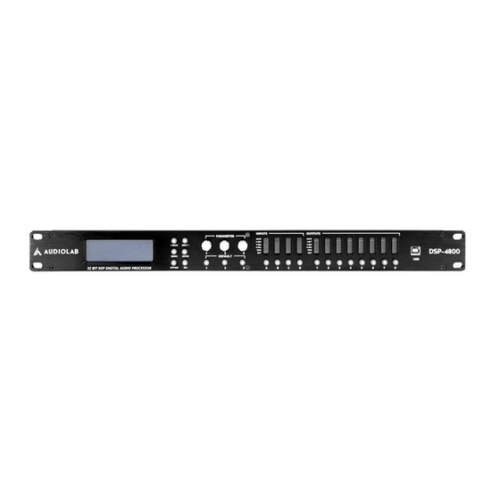
1. FRONT PANEL AND REAR PANEL CONTROLS AND CONNECTORS FRONT PANEL Features: • Use 32 bits floating point unit, made the opera- tion precision more higher. • Use 96KHz sampling frequency, one time higher than the similar products in the market. Sound more nicety, less distortion. • PC long-distance control by use the attached software: Short distance can be control by con- necting WIFI, USB connecter or RJ45(LAN) con- necter. - Page 6 REAR PANEL 1. Power Cord. 2.Power Switch. 3. Ventilation Holes. 4. LAN Connector. 5. OUTPUT Connectors: These XLR-3-32 Balanced connectors output each channel analog audio signals. 6. INPUT Connectors: These XLR-3-31 Balanced con- nectors input each channel analog audio signals. P. 6 DSP-4800W ENGLISH VERSION...
-
Page 7: Panel Operation
2. PANEL OPERATION INPUT PARAMETER SETTING: Long press (about 3 second) “IN A/ IN B/ IN C/ IN D”, and then the relevant channel into Edit Status, yellow light display. (Each channel default for mute), Short press relevant function key set the parameter setting, press “<BACK” and “NEXT>”... - Page 8 4. Input Gain Setting: Parameter Gain, adjust range: -40.0dB-+6.0dB, Step pitch is 0.1dB. Each channel has unat- tached gain control. Example 1. Press A channel key about 3 seconds till the yellow light display, into Edit Status. 2. Press “<BACK or “NEXT>”, switch to Gain. Display next: 3. Turn the first knob of “PARA” to change the value. (Turn the knob clockwise, the value increase: Turn the knob withershins, the value decrease.) 5. EQ setting:...
-
Page 9: Output Parameter Setting
4. Press ENTER, confirm select “Lo-shelf” sta- tus, into parameter setting. Turn the first knob of “PARA” to adjust the gain value. Turn the sec- ond knob to adjust Freq. Turn the third knob to select slope. (Turn the knob clockwise, the value increases;... - Page 10 2. Signal Source Setting: Example 1. Press OUT1 channel for 3 seconds till the yel- low light display, into Edit Status of OUT1. Display next: 2. Turn the first knob “PARA” to select ON or OF, then press ENTER to confirm. 3. Output Gain Setting: Parameter Gain, adjust range: -40.0dB-+15.0dB, Step pitch is 0.1dB.
- Page 11 4. Output Polarity Setting: Parameter Polarity, +Normal: Positive, -Invert: Negative pole. Each channel has unattached phase control. Example 1. Press OUT1 channel key about 3 seconds till the yellow light display, into Edit Status of OUT1. 2. Press “<BACK or “NEXT>”, switch to Polarity. Display next: 5. Output Delay Setting: Parameter Delay, adjust range: 0ms-1000ms, 0Meter-346Meter, 0Feet-1134.88Feet.
- Page 12 6. Crossover HPF Setting: Parameter HPF, Highpass, range: 20Hz-20KHz, Selectable fiter type: Link-Riley, Bessel, Butter- worth. Selectable slope: 12dB, 18dB, 24dB, 48dB. Each channel has unattached highpass filter. Example 1. Press OUT1 channel key for about 3 seconds till the yellow light display, into Edit Status of OUT1. 2.
- Page 13 8. EQ Setting: Parameter EQ, OUT1-OUT8 Each channel can set 6 parameter EQ (EQ1-EQ6). Example A. At parameter status: Freq: 20Hz-20Khz Gain: -20dB-+15dB Bandwidth: 0.05/Oct-3/Oct B. At Lo_Shelf, Hi-shelf status: Freq: 20Hz-20Khz Gain: -30dB-+15Db Slope:+6dB, +12dB Example: 1. Press OUT1 channel for 3 seconds till yellow light displays into Edit status of OUT1.
- Page 14 9. Limiter Setting: Parameter Limiter, Out1-Out8 Each channel has unattached limiter control. Threshold value: -30dBu-20dBu. Attack: 0.3ms- 100ms Release: 2x, 4x, 6x, 16x, 32x. Example 1. Press OUT1 channel for 3 seconds till the yel- low light display, into Edit Status of OUT1. 2. Press <”BACK” or “NEXT”>, switch to Limit or Compressor, Press ENTER to confirm.
-
Page 15: System Parameter Setting
SYSTEM PARAMETER SETTING: All the setted parameter can be saved in the memo- rizer to be used in the same mode in the future. Short press <”MENU”> into function selecting: Press “BACK”, “NEXT” or turn any knob of “PARA” to go forward or back. -
Page 16: Pc Software Operation
3. PC Software Operation DSP series digital speaker processor use advanced Long-distance control technology, it can set all the func- tions and controlled by connection software. It has strong function and steady quality. Short distance can be con- trolled by USB connector or LAN connector; Long-dis- tance controlled by LAN connector;... - Page 17 Soft Vision: F. Connect Option A. Display Information DATA G. Input Channel B. Save/Load the Program Interface H. Output Channel C. Change the Channel Name I. Input Source Setting D. Copy, Edit. J. Channel Connect E. Change the System Setting Connection: (Please confirm to use the connection line; connect the computer and product. Please see the attached CD to install the driv- er for first connection. Communication Port Select Select workable computer Network Address Settings Select workable IP Address P.
- Page 18 Program A. Load/Delete a group user data or ef- fect data from the connected device. B. Store/Delete a group user or effect data to the connected device. C. Read out a group user data or effect data from the computer. D.
- Page 19 Channel Setup Click into below page, and you can change the channel name directly. Copy Channel Copy Mode selecting, Click into below page, it can set the same parameter for two channels directly. System System option, click into below page A. Change LCD backlight display time B. Change Temperature C. The details of this product will be shown on the LCD (it can be amended).
- Page 20 Common Setting as below: ON: Mute off, channel normal use. MUTE: Mute on, channel in mute. CHA: Channel in gray color means the channel’s not selected. CHA: Clicked channel can switch the selection state, se- lected channel display relevant color. SIGNAL EDIT VISION AT INPUT STATE: Each input channel setting is the same A.
- Page 21 Curve Display Vision: Drag the EQ icon (1/2/3/4/5/6) by mouse to adjust the relevant parameter. Drag the crossover icon (H/L) by mouse to adjust the relevant parameter. P. 21 DSP-4800W ENGLISH VERSION...
- Page 22 (Wired) 4. Single Processor Connection Processor Computer 1. Restore wifi module a Factory Setting in the Processor’s front panel. a. Start-up the processor b. After the screen show out the model and brand of the processor, press the “MENU” key. c. Twist to “System Submenu” with the knob, then press the “ENTER”...
- Page 23 3. Connect the computer and processor with the net line. The obtained IP address should be “10.10.100.100”. 4. Open up the software interface, click on the top right corner “Connection”. P. 23 DSP-4800W ENGLISH VERSION...
- Page 24 5. Input the IP address “10.10.100.254”. Connection Success!. Processor Router Computer 1. Restore wifi module a Factory Setting in the Processor’s front panel. a. Start-up the processor b. After the screen show out the model and brand of the processor, press the “MENU” key. c.
- Page 25 c. Click “Obtain an IP address automatically”, OK. b. Click the “Internet Protocol (TCP/IP), then click “Properties” again. P. 25 DSP-4800W ENGLISH VERSION...
- Page 26 3. Connect the computer and processor with the net line. The obtained IP address should be “10.10.100.100”. 4. After you connect the network successfully, type “10.10.100.254” on the IE browser, land to the wifi mod- ule. Input the user name: admin, password: admin, then press “OK”.
- Page 27 a. Then enter “Working Mode Configuration” Interface. (Wired) 5. Many Processors Connection b. Click on the top left corner “AP Interface Set- ting”, in-put the “Network Name (SSID)”: AB-Link. P. 27 DSP-4800W ENGLISH VERSION...
- Page 28 c. Setting in underlying “LAN Setup”. First: made the “DHCP Type” into “Disable”: Second: Made the IP address of Wifi module as the same as Router “ 19 2 .16 8 . 0 .10 1” ( “ 19 2 .16 8 . 0 .10 2 ” ) , “192.168.0.103”, by the same token.
- Page 29 d. Click on the top left corner “Mode Selection”, Set for the “Station Mode” (terminal mold STA), apply. 5. Restart the processors. Computer connected to Router, Router connected to Processors (here with two lines or more) P. 29 DSP-4800W ENGLISH VERSION...
- Page 30 6. Open up the software interface, click on the top right cor- ner “Connection”. 7. Type the IP address “192.168.0.101”, “192.168.0.102”, “192.168.0.103” (This IP address should be the same with the DHCP IP ad- dress). Connection Successful. P. 30 DSP-4800W ENGLISH VERSION...
- Page 31 Each speaker processor connect to this systems should be set up different IP address. P. 31 DSP-4800W ENGLISH VERSION...
- Page 32 DESCRIPCIÓN • DSP-4800 W es un procesador digital todo en uno in- Filtro: 6 bandas/cada salida, 8 bandas/cada entra- alámbrico con 4 entradas y 8 salidas. La unidad usa un punto flotante de alta precisión de 32 bits y tiene una fre- •...
- Page 33 CAUTION RISK OF ELECTRIC SHOCK DO NOT OPEN - ADVERTENCIA - A. El cable de alimentación o el enchufe han sido Al utilizar productos eléctricos, siga siempre las pre- dañados, o cauciones básicas, incluidas las siguientes: B. Si objetos pequeños o líquidos han ingresado Lea esta guía antes de utilizar el producto.
- Page 34 TABLA DE CONTENIDOS 1. Panel Frontal, Panel Trasero y Conectores P. 5 2. Operación del Panel P. 7 2.1 Configuración del parámetro de entrada P. 7 P. 9 2.2 Configuración del parámetro de salida 2.3 Configuración del parámetro del sistema P. 15 3. Funcionamiento del software para PC P. 16 4. Conexión de un solo procesador P. 22 5. Conexión de varios procesadores P. 24 P.
-
Page 35: Panel Frontal, Panel Trasero Y Conectores
1. PANEL FRONTAL, PANEL TRASERO Y CONECTORES PANEL FRONTAL Descripción del Producto: • Unidad de punto flotante de 32 bits de alta precisión. • Frecuencia de muestro de 96 KHz, superior a otros productos similares del mercado. Sonido fluido y parejo con reducción de distorsión. • Control a distancia con PC y el software incluido: •... - Page 36 PANEL TRASERO 1. Cable de alimentación. 2. Interruptor de encendido/apagado 3. Ranura de ventilación 4. Conector LAN 5. Conectores de salida: Los conectores XLR-3-32 bal- anceados emiten las señales de audio analógicas de cada canal. 6. Conectores de entrada: Los conectores XLR-3-31 balanceados reciben las señales de audio analógicas de cada canal (Observación: las entras analógicas AES emplean conectores A o C únicamente.
-
Page 37: Operación Del Panel
2. OPERACIÓN DEL PANEL CONFIGURACIÓN DE PARÁMETROS DE ENTRADA: Mantenga presionadas (por 3 segundos) las teclas “IN A/ IN B /IN C /IN D” en el canal deseado, dentro del modo Edit, hasta ver la luz amarilla. (Con cada canal en si- lencio por defecto) Seleccione la función deseada en el menú Parameter. Presione “<BACK” o “NEXT>” para ac- ceder a la configuración de dicha función y luego ENTER para confirmar. - Page 38 4. Configuración de la ganancia de entrada: Parámetro Ganancia, regular rango: -0,0 dB - +6,0 dB. Step pitch 0,1 dB. Cada canal cuenta con control individual de ganancia. Ejemplo 1. Presione la tecla del canal A por 3 segundos, hasta visualizar la luz amarilla en el modo Edit. 2. Presione “<BACK” o NEXT>” para acceder a Gain. En la pantalla verá: 3.
-
Page 39: Configuración Del Parámetro De Salida
4. Presione “ENTER” para confirmar la selección de “Lo-shelf”. Gire la primera perilla de “PARR” para regular el valor de ganancia. Utilice la se- gunda perilla para la frecuencia, y la tercera perilla para seleccionar la pendiente. (Gire la perilla en sentido horario para incrementar el valor o en sentido antihorario para disminuirlo). - Page 40 2. Configuración de la fuente de señal: Example 1. Presione el canal Out1 por 3 segundos, hasta visualizar la luz amarilla en el modo Edit. En la pantalla verá: 2 Gire la primera perilla de “PARR” para selec- cionar entre On (encendido) y Off (apagado). Presione ENTER para confirmar. 3. Configuración de la ganancia de salida: Parámetro Ganancia.
- Page 41 4. Configuración de la polari- dad de salida: Parámetro Polaridad. [+Normal]: Positiva. [-In- vertida]: negativa. Cada canal cuenta con control individual de fase. Ejemplo 1. Presione el canal Out1 por 3 segundos, hasta visualizar la luz amarilla en el modo Edit. 2. Presione “<BACK” o “NEXT>” para seleccion- ar Polarity.
- Page 42 6. Configuración de transición del filtro de paso de agudos (HPF): Parámetro HPF, paso de agudos. Rango: 20 Hz - 20 KHz. Filtro seleccionable: Butterworth, Link-Riley, Besse! Pendiente seleccionable: 12 dB, 18 dB, 24 dB, 48 dB. Cada canal cuenta con HPF individual. Ejemplo 1. Presione el canal Out1 por 3 segundos, has- ta visualizar la luz amarilla en el modo Edit. Pre- sione “<BACK” o “NEXT>”...
- Page 43 8. Configuración del Ecualizador: Parámetro EQ, OUT1-OUT8 Cada canal puede establecer 6 parámetros EQ (EQ1-EQ6). Ejemplo A. En modo Parameter: Frecuencia: 20Hz-20Khz Ganancia: -20dB-+15dB Ancho de Banda: 0.05/Oct-3/Oct B. En modo meseta de bajos (low shelf) y mese ta de altos (Hi-shelf): Frecuencia: 20Hz-20Khz Ganancia: -30dB-+15Db Pendiente:+6dB, +12dB Ejemplo: 1.
- Page 44 9. Configuración del limitador: Parámetro Limitador, Out1-Out8. Cada canal cuenta con control de limitador individual Valor de umbral: -30 dBu - 20 dBu. Arranque: 0,3 ms - 100 ms. Tiempo de release: 2x,4x,6x,8x,16x,32x. Ejemplo 1. Presione el canal Out1 por 3 segundos, hasta visualizar la luz amarilla en el modo Edit. 2.
-
Page 45: Configuración Del Parámetro Del Sistema
CONFIGURACIÓN DE PARÁMETROS DEL SISTEMA: Todos los parámetros establecidos se pueden guard- ar en la memoria para volver a utilizarlos en el futuro. Presione la tecla “MENU”. Luego, presione “<BACK”, “NEXT>” o gire las perillas de “PARR” para desplazarse hacia adelante y atrás. Presione “ENTER” en la función deseada. -
Page 46: Funcionamiento Del Software Para Pc
3. Panel de Control L a serie DSP de procesadores digitales utiliza tecnología de control a larga distancia de avanzada. El usuario puede configurar todas las funciones y contro- larlas a través de un software de conexión, de función importante y calidad constante. Por otro lado, el control a corta distancia puede realizarse con el conector USB o LAN. - Page 47 Visión del Software: F. Opciones de conexión. A. Visualización de datos. G. Canal de entrada. B. Guardar/Cargar interfaz del programa. H.Canal de salida. C. Modificar el nombre del canal. I. Config. de entrada. D. Copiar, Editar. J. Conexión de Canal E. Modificar configuración del sistema. Conexión: Confirme la línea de conexión. Conecte la computadora y el equipo. Para la primera conexión, debe instalar el driver. Utilice el CD incluido. Puerto de comunicación Seleccione la PC en la que trabajará Configuración de dirección de Red Seleccione la IP con la que trabajará...
- Page 48 Programa A. Cargar/eliminar información del usuar- io o de un efecto del dispositivo conectado. B. Almacenar/eliminar información del usu- ario o de un efecto del dispositivo conectado. C. Cargar información del usuario o un efecto en la PC. D. Recuperar toda la información del usu- ario o de un efecto en la PC.
- Page 49 Configuración del Canal Click into below page, and you can change the channel name directly. Copiar Admite modificar el nombre del canal directamente. Opción para copiar un canal. Al hacer clic, verá: El usuario puede establecer el mismo parámetro para dos canales. Sistema Opciones del sistema.
- Page 50 Configuraciones más frecuentes ON: Función de silencio apagada. Los canales funcionan normalmente. MUTE: Función silencio encendida. Canales silenciados. CHA: Éste ícono en gris indica que no hay selección. CHA: Al hacer click, se modifica el estado. Cambiará de color. EDICIÓN DE SEÑAL EN CANALES DE ENTRADA Todos los canales de entrada se configuran igual Función de silencio.
- Page 51 Visualización de la Curva: Arrastre el ícono EQ (1, 2, 3, 4, 5, 6) con el mouse para regular el parámetro Arrastre el ícono de transición (H, L) con el mouse para regular el parámetro P. 51 DSP-4800W VERSION ESPAÑOL...
-
Page 52: Conexión De Un Solo Procesador
(con Cable) 4. Conexión de un procesador Procesador 1. Restaure los ajustes de fábrica del módulo wifi en el panel frontal del procesador. a. Inicie el procesador. b. Luego de ver el modelo y la marca del procesa- dor en la pantalla, presione la tecla “MENU”. c. - Page 53 3. Conecte la PC y el procesador con la línea de red. La dirección IP obtenida debe ser “10.10.100.100”. 4. Abra la interfaz del software y luego haga clic en “Connection”. P. 53 DSP-4800W VERSION ESPAÑOL...
- Page 54 5. Ingrese la dirección IP “10.10.100.254” para logar una conexión correcta. Procesador Router 1. Restaure los ajustes de fábrica del módulo wifi en el panel frontal del procesador. a. Inicie el procesador. b. Luego de ver el modelo y la marca del procesa- dor en la pantalla, presione la tecla “MENU”.
- Page 55 c. Haga clic en “Obtener una dirección IP au- tomáticamente” y luego en “aceptar”. b. Haga clic en “Protocolo Internet (TCP/IP) y luego en “Propiedades” nuevamente. P. 55 DSP-4800W VERSION ESPAÑOL...
- Page 56 3. Conecte la PC y el procesador con la línea de red. La dirección IP obtenida debe ser “10.10.100.100”. 4. Luego de conectarse a la red, ingrese “10.10.100.254” en el navegador de IE. Proceda a escribir el nombre de usuar- io: admin y la contraseña: admin. Haga clic en “Ok”. P.
-
Page 57: Conexión De Varios Procesadores
a. Ingrese en la interfaz “Working Mode Configuration”. (con Cable) 5. Conexión varios Procesadores b. Haga clic en la opción “AP Interface Setting” y luego ingrese en “Network Name (SSID)”: AB-Link. P. 57 DSP-4800W VERSION ESPAÑOL... - Page 58 c. Diríjase al menú “LAN Setup”. En la opción “DHCP Type”, seleccione “Disable”. Coloque la dirección IP “192.168.0.101” (192.168.0.102, 192.168.0.103, etc.) para equiparar la del router y la del módulo wifi. “Apply”. P. 58 DSP-4800W VERSION ESPAÑOL...
- Page 59 d. Haga clic en la opción “Mode Selection”. Selec- cione “Station Mode” (STA Mode) y haga clic en “Apply”. 5. Reinicie los procesadores. Conecte la PC al router, y el router a los procesadores (con dos o más líneas de red). P. 59 DSP-4800W VERSION ESPAÑOL...
- Page 60 6. Abra la interfaz del software y luego click en “Connection”. 7. Coloque la dirección IP “192.168.0.101”, “192.168.0.102”, “192.168.0.103” y se habrá conectado correctamente. La di- rección IP debe ser la misma que en “DHCP IP”. P. 60 DSP-4800W VERSION ESPAÑOL...
- Page 61 Procesor Digital 1 Procesor Digital 2 Procesor Digital 250 El conector LAN del panel dorsal permite unir hasta 250 unidades. Cada procesador conectado a este sistema debe contar con su propia dirección de IP Each speaker processor connect to this systems should be set up different IP address. P. 61 DSP-4800W VERSION ESPAÑOL...
- Page 62 FOR MORE INFO ON THIS PRODUCT PLEASE CHECK WWW.AUDIOLAB-WEB.COM PARA MAS INFORMACION SOBRE ESTE PRODUCTO VISITE WWW.ADUIOLAB-WEB.COM...
Need help?
Do you have a question about the DSP-4800 W and is the answer not in the manual?
Questions and answers