Advertisement
Quick Links
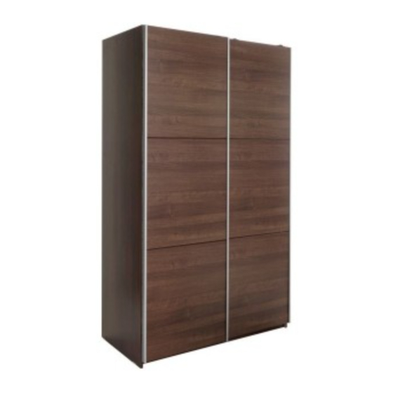
Bergen 150 Foil/foil
Assembly Instructions
Dimensions
Width - 150cm
Depth - 59.5cm
Height - 199.8cm
carton(s) it was packed in.
Important
– Please read these instructions fully before starting assembly
If you need help or have damaged or missing parts, please visit: www.argos-support.co.uk
or email: Help@ClickSpares.co.uk (quoting your original order number)
Alternatively, call the Spares Helpline on: 0370 112 1928
For any other queries please contact the Customer Helpline on: 0345 640 2020
- Please keep for future reference
Tip : To prevent damage,
we recommend that you
build your unit on the
246/9577 OAK
244/0204 WHT
227/6306 WAL
246/9577
244/0204
227/6306
Issue 3 - 05/11/15
Advertisement

Summary of Contents for hygena 246/9577
- Page 1 Dimensions Tip : To prevent damage, Width - 150cm we recommend that you Depth - 59.5cm build your unit on the 246/9577 OAK Height - 199.8cm carton(s) it was packed in. 244/0204 WHT 227/6306 WAL Important – Please read these instructions fully before starting assembly If you need help or have damaged or missing parts, please visit: www.argos-support.co.uk...
-
Page 2: Handy Hints
Safety and Care Advice Important – Please read these instructions fully before starting assembly • Check you have all the • Do not stand or put weight on •To reduce the components and tools listed on the product, this could cause likelihood of damaging your pages 2 and 3. - Page 3 Components - Panels For damaged or missing parts, please visit: www.argos-support.co.uk or email: Help@ClickSpares.co.uk Please check you have all the panels listed below Right side Upright Foldy back x2 Left side (199.8 x 52.9cm) (199.8 x 55.8cm) (190.3 x 49cm) (193 x 74cm) P2883 P2882...
- Page 4 Components - Fittings For damaged or missing parts, please visit: www.argos-support.co.uk or email: Help@ClickSpares.co.uk Please check you have all the fittings listed below Note: The quantities below are the correct amount to complete the assembly. In some cases more fittings may be supplied than are required.
-
Page 5: Tools Required
Components - Fittings Please check you have all the fittings listed below Note: The quantities below are the correct amount to complete the assembly. In some cases more fittings may be supplied than are required. ZF9997I ZF9997K ZF9997L Screw x 2 Screw x 7 Screw x 33 (3.5x35mm) - Page 6 Assembly Instructions Step 1 Cabinet assembly Screw 9 locking screws B into the holes on back of the left side 1. Mount hanger rail support K, fasten with 1 screw D. Screw D into the board between two predrilled holes. Mount tapping block for Finished guide rail f with two...
- Page 7 Assembly Instructions Step 1 Cabinet assembly Insert 6x small locking nuts I into the top 5. Make sure the ‘arrow’ on I is pointing towards the Finished hole in the edge of the top front edge Insert 6x small locking nuts I into the bottom 6.
- Page 8 Assembly Instructions Assembly Instructions Step x Step 1 Xxxxxx Cabinet assembly Attach top 5 with 2x confirmat screws A to the upright 3. Use allenkey Attach bottom 6 with 2x confirmat srews A to the Finished upright 3 front edge Plain chipboard Attach 2x the shelf 8 to the upright 3 with 3x...
- Page 9 Assembly Instructions Step 1 Cabinet assembly Attach 2x the plinth 7 between the left site 1 and the right side 2. Note: that the finished side properly placed. Attach the right side 2 with 9x double locking screws G on the top 5, shelf 8 and the bottom 6.
- Page 10 Assembly Instructions Step 1 Cabinet assembly Position L-Bracket M onto top 5 , by using 1x screw C. Position metal guide rail Q onto top 5 , fix with 6x screws C. Attach 2x end stop g on the end of the guide rail Q with 2x screws d.
- Page 11 Assembly Instructions Step 2 3 Segment slide door left Put 8x nylon plug E into the segment 9 . Use a small hammer. Repeat this step. Mount door trim U with 3x screws C on segment Note: there should be no gap between doorsegment 9 and door trim U.
- Page 12 Assembly Instructions Step 2 See page 2 for link to instruction video! 3 Segment slide door left Mount 2x connecting plate O, each with 2x screws D on segment 9 and 2x screws D on middle segment 0 . Remove protective film from door handle S.
- Page 13 Assembly Instructions Step 3 See page 2 for link to instruction video! Place left slide door Hook the 2x back guide part j into the plastic guide rail R. Detail. The hook of the back guide part j should be in the front guide of the plastic guide rail R...
- Page 14 Assembly Instructions Step 3 Place left slide door Hook Sliding door connecting platek on metal guide rail Q. Detail. The wheel of the sliding door connecting plate k should be in the front guide of the metal guide rail Q. To lock the door, lock the Sliding door connecting plate k on the guide...
- Page 15 Assembly Instructions Step 4 3 Segment slide door right Put 8x nylon plug E into the segment 9. Use a smallhammer. Repeat this step. Mount door handle S with 4x screws C on segment 9 . Note: there should be no gap between doorsegment 9 and door handle S.
- Page 16 Assembly Instructions Step 4 See page 2 for link to instruction video! 3 Segment slide door right Mount 2x connecting plate O, each with 2x screws D on segment 9 and 2x screws D on middle segment 0 . Remove protective film from door handle S.
- Page 17 Assembly Instructions Step 5 See page 2 for link to instruction video! Place right slide door Hook the 2x front guide part i into the plastice guide rail R. Detail. The hook of the front guide part i should be in the rear guide of the plastic guide rail R...
- Page 18 Assembly Instructions Step 5 Place right slide door Hook the sliding door connecting bracketl on metal guide rail Q. Detail. The wheel of the sliding doorconnecting bracket l should be in the rear guide of the metal guide rail Q. To lock the door, lock the sliding door connecting bracket l on the...
- Page 19 Assembly Instructions Step 6 Place cabinet Use to 1x wall plug W to mount L-Bracket M on the wall, please see last page for more information. Before adjusting the doors, use a spirit level to check if the base of this unit is level front-to-back and side-to-side in the three positions shown.
-
Page 20: A Guide To - Wall Mounting & Fixings
A Guide to - Wall Mounting & Fixings Important: When drilling into walls always Important note: check that there are no hidden wires or pipes etc. If plastic wall plugs Make sure that the screws and wall plugs being used are supplied with your are suitable for supporting your unit.
Need help?
Do you have a question about the 246/9577 and is the answer not in the manual?
Questions and answers