
Summary of Contents for QUBINO ZMNHAD1
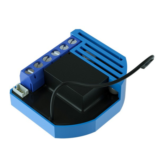
- Page 1 USER MANUAL EN. QUBINO FLUSH 1 RELAY The Qubino Flush 1 Relay is ideal for remotely controlling one light or electrical device (door lock, door opener, small appliances, etc.).
-
Page 2: Table Of Contents
2.3. Installation examples where Flush 1 Relay is installed in electrical box......................13 2.4. Additional features of Flush 1 Relay which can make your life easier....................... 14 3. Qubino Flush 1 Relay Advantages and Highlights ................................. 16 3.1. Advantages ..........................................16 3.2. -
Page 3: About Qubino
About Qubino Qubino is a family of innovative Z-Wave devices, many of them the smallest of their kind. Numerous breakthrough innovations, 100% quality control, and responsive customer service make Qubino the number one choice for making your life more comfortable. - Page 4 About Z-Wave: The Z-Wave protocol is an interoperable, wireless, RF-based communications technology designed specifically for control, monitoring, and status reading applications in residential and light commercial environments. Mature, proven, and broadly deployed (with over 50 million products sold worldwide), Z-Wave is by far the world market leader in wireless control, bringing affordable, reliable, and easy-to-use 'smart' products to millions of people in every aspect of daily life.
-
Page 5: Safety Information
Safety Information For Qubino, safety is first, so we have prepared lots of safety tips and information that can be found throughout this manual. To ensure your safety, please read this manual carefully before installing the device; follow the instructions exactly. The manufacturer (GOAP d.o.o. Nova Gorica) shall not be legally responsible for any equipment damage or personal injury caused by incorrect installation or operation other than that covered in this manual. -
Page 6: Flush 1 Relay - Available Frequencies
Flush 1 Relay - Available Frequencies ORDERING CODE POWER SUPPLY FREQUENCY Z-WAVE FREQUENCY* (MODEL NUMBER) ZMNHAD1 50/60 Hz 868,4 MHz ZMNHAD2 50/60 Hz 921,4 MHz ZMNHAD3 50/60 Hz 908,4 MHz ZMNHAD4 50/60 Hz 869,0 MHz ZMNHAD5 50/60 Hz 916,0 MHz... -
Page 7: Where To Buy
The connection of a digital temperature sensor means you can create complex scenes and control any device relative to a set temperature range. The Qubino Flush 1 Relay also acts as a Z-Wave repeater to improve the range and stability of the Z-Wave network. - Page 8 Flush 1 Relay supported functions: Turn Temperature Scene 1 Scene 2 Automatically Associations Z-Wave Auto- ON/OFF Measurement Measurement Sensor Trigger Trigger turn ON/OFF Repeater inclusion ✓ ✓ ✓ ✓ ✓ ✓ ✓ ✓ ✓ ✓...
-
Page 9: Use Cases
We have prepared a few of them for you so you can get an idea for your next smart home project. Of course, there are countless of other options for how to use Qubino Flush 1 Relay to remotely control devices via your smartphone. - Page 10 • Remotely trigger different scenes with temperature sensor is sold separately - for two additional inputs (I2, I3) – for more info, please see Qubino catalogue. example scene 1: turn on all the lights in Product ordering code (model number):...
-
Page 11: Installation Examples Where Flush 1 Relay Is Installed Behind A Power Socket - For Switching Device On/Off And Measuring Power Consumption Of The Connected Device
2.2. Installation examples where Flush 1 Relay is installed behind a power socket – for switching device on/off and measuring power consumption of the connected device • Remotely control an oven connected to a • Remotely control an iron connected to a power socket power socket •... -
Page 12: Installation Examples Where Flush 1 Relay Is Installed Behind A Power Socket - For Measuring Power Consumption Of The Connected Device
2.3. Installation examples where Flush 1 Relay is installed behind a power socket – for measuring power consumption of the connected device • Remotely measure power consumption of • Remotely measure power consumption refrigerator connected to a power socket of microwave oven connected to a power socket •... -
Page 13: Installation Examples Where Flush 1 Relay Is Installed In Electrical Box
(*The temperature sensor is sold (*The temperature sensor is sold separately - for more info, check Qubino separately - for more info, check Qubino catalogue. Product ordering code: catalogue. -
Page 14: Additional Features Of Flush 1 Relay Which Can Make Your Life Easier
2.4. Additional features of Flush 1 Relay which can make your life easier • Do you worry that your irrigation system • Do you often forget to turn off devices can expose your garden to flooding? when you leave your home, like lights in the basement or attic? •... - Page 15 (hub) needs to support this and automatically trigger another Z- feature). Know how much power your light, Wave device. And have other Z-Wave domestic water tank, iron, etc, is using. devices trigger your Qubino Flush 1 Relay.
-
Page 16: Qubino Flush 1 Relay Advantages And Highlights
All this is possible because the Qubino Flush 1 Relay is the smallest Z- Wave switch in the world. - Page 17 • The Qubino Flush 1 Relay is the only Z-Wave switch in the world that has two additional inputs (I2, I3), which enable triggering of different scenes. The user does not need to buy additional devices for setting various scenes. For example: o Switch connected to input I2: Welcome Home –...
- Page 18 • By scanning the QR code on the back of your Qubino device, the serial and part numbers will be automatically copied on your mobile phone; they also provide direct access to Qubino’s technical support team. The serial and part numbers of your device are given automatically every time you open an inquiry with our support team: this instantly shares the relevant device information we need to provide the best technical support possible.
-
Page 19: Highlights
3.2. Highlights • Remote (via smartphone or PC) and local on/off control of bulbs and other electrical devices • Works with push-button (momentary switch) and toggle switch or you can install it behind power sockets • Capable of measuring the power consumption of the connected device in real time via smartphone, which allows you to save on electricity bills* •... -
Page 20: Package Contents
4. Package Contents • Flush 1 Relay Device • Installation Manual... -
Page 21: Technical Terms For Switches
5. Technical Terms for Switches Symbol Switch example images Definition Qubino Other names Single pole, single throw Two-way (SPST) - One Switch; One-way switch Toggle switch Bi-stable switch (regular switch controlling one switch switch) light / circuit of lights Single pole,... - Page 22 Qubino devices are installed into flush mounting boxes behind the switches. You can see some examples below: For more information on how to install your device, please refer to the Installation chapter.
-
Page 23: Compatibility With Z-Wave Gateways (Hubs)
Please check compatibility with your Z-Wave gateway (hub) before you purchase this device. If you don’t see your gateway (hub) in the table below, please contact us at: http://qubino.com/support/#email. ⓘ Please note that the gateway (hub) compatibility was tested on 1.7.2017 and it may not include the latest testing data. -
Page 24: Installation
7. Installation Before installing the device, please read the following carefully and follow the instructions exactly: ⓘ Danger of electrocution! Installation of this device requires a great degree of skill and may be performed only by a licensed and qualified electrician. Please keep in mind that even when the device is turned off, voltage may still be present in the device’s terminals. -
Page 25: Installing The Device Behind A Light Switch
7.1. Installing the device behind a light switch The installation process, tested and approved by professional electricians, consists of the following simple steps: Step 1 – Turn OFF the fuse: • To prevent electrical shock and/or equipment damage, disconnect electrical power at the main fuse or circuit breaker before installation and maintenance. - Page 26 Step 2 – Installing the device: • Connect the device exactly according to the diagrams shown below Before Qubino installation:...
- Page 27 After Qubino installation: Wiring with one switch...
- Page 28 INSTALLATION WITH ON/OFF SWITCH AND SCENE SWITCHES:...
- Page 29 INSTALLATION WITH 2 OR MORE SWITCHES CONTROLLING THE SAME LIGHT: Before Qubino installation:...
- Page 30 2 WAY SWITCH:...
- Page 31 MULTI-WAY SWITCHES:...
- Page 32 INSTALLATION WHERE THERE IS NO NEUTRAL LINE (N) IN SWITCH BOX Before Qubino installation:...
- Page 33 After Qubino installation:...
- Page 34 ⓘ Note! • Place the antenna as far as possible from metal elements as they may cause signal interference. • Do not shorten the antenna. The device’s antenna should be as upright as possible. This ensures the device’s operational range is maximized (up to 98 feet (30 m) line of sight).
- Page 35 Step 3– Turn ON the fuse:...
- Page 36 Step 4 – Add the device to your Z-Wave network: • For more details on how to include the device, please refer to the Z-Wave Inclusion chapter.
- Page 37 Step 5 – The Installation is now complete. It’s time to make your life more comfortable with the help of the Qubino Flush 1 Relay...
-
Page 38: Installing The Device Behind A Socket
7.2. Installing the device behind a socket Step 1 – Turn OFF the fuse:... - Page 39 Step 2 – Install the device:...
- Page 40 Step 3 – Turn ON the fuse: Step 4 – Add the device to your Z-Wave network:...
- Page 41 Step 5 – The Installation is now complete. It’s time to make your life more comfortable with the help of the Qubino Flush 1 Relay...
-
Page 42: Installing The Qubino Temperature Sensor
7.3. Installing the Qubino Temperature Sensor The temperature sensor is a Qubino accessory and is sold separately - for more info, please see the Qubino product catalogue or website: http://qubino.com/products/accessories/ Product ordering code: ZMNHEA1 Qubino Z-Wave devices have the option to connect a temperature sensor (sold separately), which allows you to remotely monitor ambient or water temperature. - Page 43 Temperature sensor installation example: Step 1 – Exclude the device (if it is already connected to your Z-Wave system) Step 2 – Switch of the power supply...
- Page 44 Step 3 – Connect the temperature sensor as shown below Step 4: Place the temperature sensor in the switch box...
- Page 45 Step 5 – Turn the fuse on Step 6 – Re-include the device to your network...
- Page 46 Step 7 – Start using the temperature sensor in connection with your device...
-
Page 47: Device Information And Support
By scanning the QR code on the back of your Qubino, its device title, serial number, and part number are automatically copied to your mobile phone. You can also use the code for direct access to the device page for more information. -
Page 48: Electrical Diagram (110 - 230Vac, 24Vdc)
9. Electrical Diagram (110 - 230VAC, 24VDC) Notes for diagram: Neutral wire (+VDC) Live (line) wire (-VDC) Output for electrical device (load) no. 1 ⬆ Input for switch /push button or sensor Input for switch /push button or sensor Input for switch /push button Temperature sensor terminal Wago 221-413 splicing connectors for L and N connection must be used only when connected to 230 VAC. -
Page 49: Adding The Device To A Z-Wave Network (Inclusion)
10. Adding the device to a Z-Wave network (Inclusion) AUTOMATICALLY ADDING THE DEVICE TO A Z-WAVE NETWORK (AUTO INCLUSION) 1. Enable add/remove mode on your Z-Wave gateway (hub) 2. Connect the device to the power supply (with the temperature sensor already connected – sold separately*). -
Page 50: Removing The Device From A Z-Wave Network (Exclusion)
11. Removing the device from a Z-Wave network (Exclusion) REMOVAL FROM A ZWAVE NETWORK (Z-WAVE EXCLUSION) 1. Connect the device to the power supply 2. Make sure the device is within direct range of your Z-Wave gateway (hub) or use a hand-held Z-Wave remote to perform exclusion 3. -
Page 51: Associations
12. Associations Use associations for direct communication between the Flush 1 Relay and other devices within your Z-Wave network without the need of your primary gateway (hub). Association Groups: Root device: • Group 1: Lifeline group (reserved for communication with the primary gateway (hub)), 1 node allowed. -
Page 52: Configuration Parameters
13. Configuration Parameters Parameter no. 1 – In-wall Switch Type for Load 1 (Q ⬆ ) to control I1 With this parameter, you can select between push-button (momentary) and on/off toggle switch types. Values (size is 1 byte dec): • default value 1 •... - Page 53 Parameter no. 3 – Input 3 contact type Values (size is 1 byte dec): • default value 0 • 0 - NO (normally open) input type • 1 - NC (normally close) input type Parameter no. 10 - Activate / deactivate ALL ON / ALL OFF Functionality Flush 1 Relay device responds to commands ALL ON / ALL OFF that may be sent by the primary or secondary gateway (hub) within the Z-Wave network.
- Page 54 Parameter no. 11 - Turn Load 1 (Q ) Off Automatically with Timer ⬆ If Load 1 (Q ) is ON, you can schedule it to turn OFF automatically after a period of time defined ⬆ in this parameter. The timer is reset to zero each time the device receives an ON command, either remotely (from the gateway (hub) or associated device) or locally from the switch.
- Page 55 Parameter no. 15 - Set Timer Units to Seconds or Milliseconds Choose if you want to set the timer in seconds or milliseconds in parameters 11 and 12. Values (size is 1 byte dec): • default value 0 • 0 – timer set in seconds •...
- Page 56 Parameter no. 40 – Watt Power Consumption Reporting Threshold for Q Load ⬆ Choose by how much power consumption needs to increase or decrease to be reported. Values correspond to percentages so if 10 is set (by default), the device will report any power consumption changes of 10% or more compared to the last reading.
- Page 57 Parameter no. 63 – Choose Normally Closed or Normally Open for Q Load ⬆ Set value determines the type of the device connected to the Q output. The output type can ⬆ be normally open (NO) or normally closed (NC). Values (size is 1 byte dec): •...
- Page 58 • 6 - Smoke Alarm; Smoke detected, unknown location • 0 - Endpoint, I2 disabled -sensor binary (9): GENERIC_TYPE_SENSOR_BINARY, SPECIFIC_TYPE_NOT_USED Values (size is 1 byte dec): • 9 - Sensor binary NOTE 1: After changing the values of the parameter, first exclude the device (without setting the parameters to their default values), then wait at least 30 seconds to re-include the device! NOTE 2: When the parameter is set to value 9 the notifications are sent for the Home Security notification type.
- Page 59 • 2 - CO; Carbon Monoxide detected, unknown location • 3 - CO2; Carbon Dioxide detected, unknown location • 4 - Water Alarm; Water Leak detected, unknown location • 5 - Heat Alarm; Overheat detected, unknown location • 6 - Smoke Alarm; Smoke detected, unknown location •...
- Page 60 Parameter no. 110 – Temperature Sensor Offset Settings Set value is added to or subtracted from the actual measured value to adjust the temperature report sent by an external sensor (sold separately). This parameter only applies to Celsius temperature unit (the Fahrenheit unit is currently not supported). Values (size is 2 byte dec): •...
-
Page 61: Technical Specifications
14. Technical Specifications Power supply 110 - 230 VAC ±10% 50/60Hz, (24-30VDC) Rated load current of AC/DC output 1 X 10A (230VAC) / (resistive load)* 1 X 10A / 30VDC Output circuit power of AC/DC 2300W (230VAC) / output (resistive load) 240W (24VDC) Power measurement accuracy P=5-50W, +/-3W... - Page 62 (CFL), low CFL* voltage halogen bulbs with electronic transformer LVH Electronic transformer: 800W (230VAC) / 380W (110VAC) Low voltage halogen bulbs with conventional transformer Other type of loads * Please contact Qubino support regarding marked load types: http://qubino.com/support/#email...
-
Page 63: Z-Wave Command Classes
15. Z-Wave Command Classes ZWAVEPLUS_INFO_REPORT_ROLE_TYPE_SLAVE_ALWAYS_0N GENERIC_TYPE_SWITCH_BINARY SPECIFIC_TYPE_POWER_SWITCH_BINARY Z-Wave Supported Command Classes: COMMAND_CLASS_ZWAVEPLUS_INFO_V2, COMMAND_CLASS_VERSION_V2, COMMAND_CLASS_MANUFACTURER_SPECIFIC_2, COMMAND_CLASS_DEVICE_RESET_LOCALLY_1, COMMAND_CLASS_POWERLEVEL_V1, COMMAND_CLASS_BASIC_V1, COMMAND_CLASS_SWITCH_ALL_V1, COMMAND_CLASS_SWITCH_BINARY_V1, COMMAND_CLASS_SENSOR_BINARY_V1, COMMAND_CLASS_METER_V4, COMMAND_CLASS_SENSOR_MULTILEVEL_V7, COMMAND_CLASS_MULTI_CHANNEL_V4, COMMAND_CLASS_ASSOCIATION_V2, COMMAND_CLASS_MULTI_CHANNEL_ASSOCIATION_V3, COMMAND_CLASS_ASSOCIATION_GRP_INFO_V2, COMMAND_CLASS_CONFIGURATION_V1, COMMAND_CLASS_MARK, COMMAND_CLASS_BASIC_V1... - Page 64 Endpoint 1 Device Class: ZWAVEPLUS_INFO_REPORT_ROLE_TYPE_SLAVE_ALWAYS_0N GENERIC_TYPE_SWITCH_BINARY SPECIFIC_TYPE_POWER_SWITCH_BINARY Command Classes: COMMAND_CLASS_ZWAVEPLUS_INFO_V2 COMMAND_CLASS_VERSION_V2 COMMAND_CLASS_BASIC_V1 COMMAND_CLASS_SWITCH_ALL_V1 COMMAND_CLASS_SWITCH_BINARY_V1 COMMAND_CLASS_METER_V4 COMMAND_CLASS_ASSOCIATION_V2 COMMAND_CLASS_MULTI_CHANNEL_ASSOCIATION_V3 COMMAND_CLASS_ASSOCIATION_GRP_INFO_V2 COMMAND_CLASS_MARK COMMAND_CLASS_BASIC_V1 Endpoint 2 (I2): Device Class: ZWAVEPLUS_INFO_REPORT_ROLE_TYPE_SLAVE_ALWAYS_0N GENERIC_TYPE_SENSOR_NOTIFICATION SPECIFIC_TYPE_NOTIFICATION_SENSOR Command Classes: COMMAND_CLASS_ZWAVEPLUS_INFO COMMAND_CLASS_VERSION_V2 COMMAND_CLASS_SENSOR_BINARY...
- Page 65 COMMAND_CLASS_BASIC COMMAND_CLASS_NOTIFICATION_V5 COMMAND_CLASS_ASSOCIATION_V2 COMMAND_CLASS_MULTI_CHANNEL_ASSOCIATION_V3 COMMAND_CLASS_ASSOCIATION_GRP_INFO_V2 COMMAND_CLASS_MARK COMMAND_CLASS_BASIC Endpoint 3 (I3): Device Class: ZWAVEPLUS_INFO_REPORT_ROLE_TYPE_SLAVE_ALWAYS_0N GENERIC_TYPE_SENSOR_NOTIFICATION SPECIFIC_TYPE_NOTIFICATION_SENSOR Command Classes: COMMAND_CLASS_ZWAVEPLUS_INFO_V2 COMMAND_CLASS_VERSION_V2 COMMAND_CLASS_SENSOR_BINARY_V1 COMMAND_CLASS_BASIC_V1 COMMAND_CLASS_NOTIFICATION_V5 COMMAND_CLASS_ASSOCIATION_V2 COMMAND_CLASS_MULTI_CHANNEL_ASSOCIATION_V3 COMMAND_CLASS_ASSOCIATION_GRP_INFO_V2 COMMAND_CLASS_MARK COMMAND_CLASS_BASIC_V1...
- Page 66 Endpoint 4: Device Class: ZWAVEPLUS_INFO_REPORT_ROLE_TYPE_SLAVE_ALWAYS_0N GENERIC_TYPE_SENSOR_MULTILEVEL SPECIFIC_TYPE_ROUTING_SENSOR_MULTILEVEL Command Classes: COMMAND_CLASS_ZWAVEPLUS_INFO_V2 COMMAND_CLASS_VERSION_V2 COMMAND_CLASS_ASSOCIATION_V2 COMMAND_CLASS_MULTI_CHANNEL_ASSOCIATION_V3 COMMAND_CLASS_ASSOCIATION_GRP_INFO_V2 COMMAND_CLASS_SENSOR_MULTILEVEL_V7 NOTE 1: The Endpoint 4 command class list only applies if an external digital temperature sensor (sold separately) is connected to the TS terminal. If the sensor is not connected, the following command class is not supported by the device: COMMAND_CLASS_SENSOR_MULTILEVEL_V7 This device can be included and operated in any Z-Wave network with other Z-Wave certified...
- Page 67 COMMAND_CLASS_METER • Default values: o Rate Type = 1 (Import) Scale = 0 (kWh)
-
Page 68: Important Disclaimer
(hub) or shows up incorrectly, you may need to change the device type manually and make sure your gateway (hub) supports multi-channel devices. Contact us for help before returning the device: http://qubino.com/support/#email 17. Warning Do not dispose of electrical appliances as unsorted municipal waste, use separate collection facilities. - Page 69 Declaration of Conformity Qubino Flush 1 Relay device is in compliance with the essential requirements and other relevant provisions of the Low voltage (LVD) Directive (2014/35/EU), Electromagnetic Compatibility (EMC) Directive (2014/30/EU), Radio Equipment Directive (2014/53/EU), Directive RoHS (2011/65/EU) and Directive ErP (2009/125/EC).
Need help?
Do you have a question about the ZMNHAD1 and is the answer not in the manual?
Questions and answers