Fujitsu ARYA45LCTU Service Manual
Refrigerant r410a, indoor/outdoor unit, duct type 50hz
Hide thumbs
Also See for ARYA45LCTU:
- Service manual (21 pages) ,
- Service manual (23 pages) ,
- Service manual (30 pages)
Table of Contents
Advertisement
SPLIT TYPE
AIR CONDITIONER
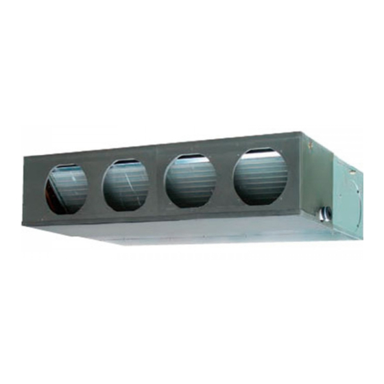
DUCT TYPE (50Hz)
Indoor unit
ARYA45LCTU AOYA45LCTL
CONTENTS
SPECIFICATIONS . . . . . . . . . . . . . . . . . .
DIMENSIONS. . . . . . . . . . . . . . . . . . . . . .
CIRCUIT DIAGRAM . . . . . . . . . . . . . . . . .
INDOOR PCB CIRCUIT DIAGRAM . . . . .
ERROR DETECTION. . . . . . . . . . . . . . .
PARTS (INDOOR UNIT) . . . . . . . . . . . .
PARTS (OUTDOOR UNIT) . . . . . . . . . .
ACCESSORIES . . . . . . . . . . . . . . . . . . .
Outdoor unit
1
2
4
5
6
9
. . .
15
20
23
26
Advertisement
Table of Contents

Subscribe to Our Youtube Channel
Related Manuals for Fujitsu ARYA45LCTU


Summary of Contents for Fujitsu ARYA45LCTU
-
Page 1: Table Of Contents
DUCT TYPE (50Hz) Indoor unit Outdoor unit ARYA45LCTU AOYA45LCTL CONTENTS SPECIFICATIONS ....DIMENSIONS..... . -
Page 2: Specifications
SPECIFICATIONS ELECTRICAL DATA NOISE LEVEL High Cooling & Heating 42 dB TYPE INDOOR UNIT ARYA45LCTU Medium 38 dB INDOOR UNIT OUTDOOR UNIT AOYA45LCTL 32 dB Quiet COOLING CAPACITY 12.0 kW 28 dB HEATING CAPACITY 13.3 kW Cooling 55 dB OUTDOOR UNIT... -
Page 3: Dimensions
DIMENSIONS INDOOR UNIT (Unit : mm) 1,177 1,015 1,135 2011.02.24... - Page 4 OUTDOOR UNIT (unit : mm) air flow 2011.02.23...
-
Page 5: Refrigerant System Diagram
REFRIGERANT SYSTEM DIAGRAM OUTDOOR UNIT INDOOR UNIT Refrigerant Pipe Pressure 15.88mm (5/8") Check Valve 3-way Valve Muffler Pressure Sensor 4-way Valve Heat Heat Check Exchanger Exchanger Valve High Pressure Accumulator Switch Muffler Compressor Refrigerant Pipe 9.52mm (3/8") Strainer Strainer Expansion 3-way Valve Valve Thermistor (Room) -
Page 6: Circuit Diagram
OUTDOOR UNIT HIGH PRESSURE SWITCH CN101 WHITE BLACK WHITE THERMISTOR ( OUTDOOR TEMP. ) CN61 WHITE BLACK WHITE BLACK WHITE THERMISTOR ( PIPE TEMP. ) BLACK WHITE CIRCUIT WHITE CN63 CONTROLLER PCB ASSY CN401 BLACK CN40 WHITE THERMISTOR ( PIPE - MID. TEMP. ) DIAGRAM BLACK WHITE... -
Page 7: Indoor Pcb Circuit Diagram
INDOOR PCB CIRCUIT DIAGRAM THERMISTOR THERMISTOR ( ROOM TEMP. ) CN8-1 B02B-XASK-1-A CN8-2 WHITE CN7-1 CONTROL UNIT B02B-XAYK-1-A CN7-2 CN2-1 YELLOW THERMISTOR ( PIPE - MID. TEMP. ) CN2-2 EZ-0080GHSE CN5-1 CN2-3 B5P-SHF-1AA THERMISTOR CN5-2 CN2-4 WHITE CN2-5 B02B-XAKK-1-A BLACK CN15-1 CN15-2 CN15... - Page 8 INDOOR UNIT CONTROLLER PCB ASSEMBLY ( MAIN PCB ) K06AK-0806HSE-C1 R1 - R3 1SS355 10k <1/10W> x 3 B02B-XASK-1-A I C8 THERMISTOR ( ROOM TEMP. ) 13.5V NJM7812 FLOAT SWITCH 1.0k <1/10W> B02B-XAYK-1-A B03B-XARK-1-A CUSTOM CODE <F> <1/10W> <1/10W> + C2 THERMISTOR ( PIPE-ENT.
- Page 9 R103 340V 13.5V D108 D2FL20U <RS-2W> T101 C108 ZFT22B03-C 4700p 630V + C113 R111 I C26-14 CN108 1000/ R104 B2P3-VH-B <1/10W> 330k <2W> D102 NORMAL COIL 1SR139-600 C114 C109 0.01 F101 220p/ <KH> BET 3.15A - 250V C115 2.0kV D106 0.01 D101 <FNS>...
-
Page 10: Outdoor Pcb Circuit Diagram
OUTDOOR PCB CIRCUIT DIAGRAM INVERTER ASSEMBLY EZ-0101SHUE EMI FILTER RFC-10 F103 F104 EMI FILTER W100 UL1015 AC250V 30A AC250V 3.15A POWER SOURCE ZCAT2132-1130 AWG12 AC230V BLACK W102 50Hz UL1015 TM101 AWG12 UL1015 W101 ORANGE AWG12 WHITE POWER SUPPLY UL1015 I NDOOR UNIT PCB ASSEMBLY W103 UL1015... - Page 11 OUTDOOR UNIT CONTROLLER PCB ASSEMBLY ( MAIN PCB ) - 1 K10BS-1005HUE-C1 C167, C168 R163 340V 330p <CH> <1/10W> 12V-2 D200 L152 D3F60 BLm31PG121 C152 D153 220/ 3-1747052-4 RF101L2S YELLOW C214 D203 D231 AC I N R219, R220 L155 2200p 1SS355 RF301B2S 1.8k <1/4W>...
- Page 12 OUTDOOR UNIT CONTROLLER PCB ASSEMBLY ( MAIN PCB ) - 2 K10BS-1005HUE-C1 CN12 B02B-XAKK-1-A C802 L800 15V-2 BLACK 15V-2 340V Q801 P_EX_OUT1 BL02Rn1 CN800 <B> EX. OUT 1 DTA143EUA B6P-VH-B I C10-7 WHITE D801 uLN2003 R800 RD24FM FTR-F3 <1/10W> BLm18AG601 DC FAN MOTOR 1 C800 P_FM1_PWM...
- Page 13 OUTDOOR UNIT TRANSISTOR PCB ASSEMBLY ( I P M ) K10AY-1003HUE-TR0 C209 - C211, C221 C222 C302 0.1 <F> 100/ L300 <F> BL02Rn1 TM303 C332 TM101 86028 D307 86028 C161 RD24FM <F> <X7R> I PM-G TM102 TM304 86028 BLACK 86028 D100 LL25XB60 I C301...
- Page 14 OUTDOOR UNIT INDICATOR PCB ASSEMBLY K10BC-1000YUE-D0 D401 SLR-325 <ORANGE> D402 SLR-325 <ORANGE> D403 SLR-325 <ORANGE> ( CN401-1 ) D404 SLR-325 <ORANGE> ( CN401-2 ) D405 SLR-325 ( CN401-3 ) <ORANGE> ( CN401-4 ) D406 SLR-325 PUMP DOWN L1 ( CN401-5 ) <ORANGE>...
- Page 15 OUTDOOR UNIT CAPACITOR PCB ASSEMBLY K05FB-1000HUE-P0 WHITE YELLOW C200 - C203 R200 660/ 220k 450V <2W> BLUE VIOLET POWER_G 2011.01.25...
-
Page 16: Error Detection
ER R OR D ETEC TION REMOTE CONTROL Troubleshooting at the remote control This is possible only on the wired remote control. Error Error contents code Self-diagnosis If an error occurs, the following display will be shown. (“EE” will appear in the set room temperature display.) Indoor signal error Unit number Wired remote control abnormal... - Page 17 INDOOR UNIT (Option) Troubleshooting with the receiver unit display Error is displayed on the wired and Lamps show error contents by flashing as follows. wireless remote control. TIMER FILTER OPERATION Error contents Lamp Lamp Lamp 2 times 3 times Indoor signal error OPERATION 4 times Lamp (Green)
- Page 18 ERROR DETECTION OUTDOOR UNIT Indicator PCB Display when an error occurs. PUMP PEAK POWER ERROR DOWN NOISE LEDs MODE (L1) (L2) (L3) (L4) (L5) (L6) Blink (Hi speed) Buttons Check that the “ERROR” LED blinks, then press the [Enter] button once. The "POWER MODE"...
- Page 19 OUTDOOR UNIT TEST RUN Before the test run, refer to he figure and check the following items. Setting method Is the outdoor unit securely installed? Turn on the power of the outdoor unit and enter standby mode. Have you performed gas leakage inspection? PUMP PEAK (Connection joints of various pipes (flang connection, brazing))
- Page 20 OUTDOOR UNIT PUMP DOWN Procedure WARNING (1) Check the 3-way valves (both the liquid side and gas side) are opened. Never touch electrical components such as the terminal blocks except the button on (2) Turn the power on. the display board. It may cause a serious accident such as electric shock. PUMP PEAK During the pump-down operation, make sure that the compressor is turned off before...
-
Page 21: Parts (Indoor Unit)
Insulation Control Box Insulation Insulation Ref. Description Part number Intake Cover Sub Assy 9374512010 Main Panel Sub Assy 9374511013 PARTS Drain Pan Sub Assy 9374513017 Drain Cap 9356541007 INDOOR UNIT Evaporator Total Assy 9374517152 Outlet Panel Sub Assy 9374510016 Cabinet R Sub Assy 9374508020 Control Cover A Sub Assy 9374516018... - Page 22 INDOOR UNIT Ref. Description Part number Casing B 9374234011 Sirocco Fan Assy 9356531046 Base Sub Assy 9374504015 Separate Wall Assy 9374228010 Casing A 9374233014 Bracket Motor Assy 9374230013 Motor Mount 9378002012 Fan Motor 9602466016 Bracket (Eva) R 9374207015 Bracket (Eva) L 9374208012 Panel (Control Box) 9374210015...
- Page 23 INDOOR UNIT Control unit Ref. Description Part number Controller PCB Assy 9707393477 Power Supply PCB Assy 9707398151 Cap (Power) 9352173011 One Touch Bush 9374407019 Terminal 3P 9703345012 Terminal 3P 9306489045 Reactor Assy 9707457018 Control Box A 9374219018 Control Cover B 9374222018 Control Box B 9374220014...
-
Page 24: Parts (Outdoor Unit)
PARTS OUTDOOR UNIT Parts number Ref. Description Top Panel Sub Assy 9374417056 Front Panel Sub Assy 9374414109 Sevice Panel Sub Assy 9374415090 Emblem Rear 9351355005 Pipe Cover Front 9378861015 Right Panel Sub Assy 9374416189 Protective Net 9375381042 Thermo Holder 9375211011 Motor Bracket Sub Assy 9374418169 Motor DC Brushless... - Page 25 Ref. Description Parts number Terminal Cover 9380328001 Inverter Cover 9380329008 Inverter Case Main Assy 9380340003 Inverter Case Assy 9380342007 Case Bottom 9380325000 Inverter RFM A 9380375005 Inverter RFM B 9380401001 Inverter PCB Assy 9708690063 Indicator PCB Assy 9708678016 Terminal 9900203023 Power Supply PCB Assy 9708688015 Thermistor...
- Page 26 OUTDOOR UNIT Ref. Description Parts number Separate Wall Sub Assy 9374413218 Valve Plate 9378804012 Ref. Description Parts number 3-way Valve Assy 9379079006 Solenoid 9970055072 3-way Valve Assy 9379077002 4-way Valve Assy 9374425235 Compressor Plate Assy 9380344001 Discharge Pipe Assy 9371581248 Compressor 9810153005 Pressure Switch...
-
Page 27: Accessories
A C C ESSOR IES INDOOR UNIT Name and Shape Q'ty Application Part number Hanger For suspending the indoor unit from ceiling 9356563009 Special nut A 313005446653 (large flange) Special nut B 313005446759 (small flange) Coupler heat For indoor side pipe joint insulation (large pipe) 9378173569... - Page 28 OPTIONAL PARTS Exterior Parts name Model No. Summary Square UTD-SF045T flang 1065 Unit : mm Round UTD-RF204 flang Unit : mm Long-life UTD-LF25NA filte Unit : mm New amenity space can Remote be offered by installing UTD-RS100 sensor remote sensor in remote control.
- Page 29 1102G3898...
Need help?
Do you have a question about the ARYA45LCTU and is the answer not in the manual?
Questions and answers