Table of Contents
Advertisement
Quick Links
Advertisement
Table of Contents

Subscribe to Our Youtube Channel
Related Manuals for Elsner TH PF-U

Summary of Contents for Elsner TH PF-U
- Page 1 TH PF TH PF-U Indoor Sensor and Ventilation Control Item numbers TH PF-U: 40100 (white), 40101 (aluminium), 40102 (anthracite), 40103 (stainless steel) TH PF: 40110 (white), 40111 (aluminium), 40112 (anthracite), 40113 (stainless steel) Installation and Adjustment...
-
Page 2: Table Of Contents
5.2. Manual operation ....................24 5.2.1. Key functions ....................25 5.3. Operation modes ....................25 Elsner Elektronik GmbH • Sohlengrund 16 • 75395 Ostelsheim • Germany Ventilation Controls TH PF(-U) • from software version 1.0 Status: 19.04.2016 • Subject to technical changes. Errors excepted. - Page 3 The change status (software version and date) can be found in the contents footer. If you have a device with a later software version, please check www.elsner-elektronik.de in the menu area "Service" to find out whether a more up-to- date version of the manual is available.
-
Page 4: Description
(rain detector or similar) takes precedence. With TH PF-U model analogue outputs (0…10 V) pass on the measured values to other systems if needed. The housing fits into standard 55 mm switching programmes and is available in two different colours. -
Page 5: Technical Data
2 button inputs (with +24 V supply) Measuring value outputs Temperature 0...10 V (0 V = -10°C, 10 V = +50°C), (TH PF-U only) Humidity 0...10 V (0 V = 0%rF, 10 V = 100%rF). 100 Ω internal, max. load 5 kΩ... -
Page 6: Installation And Start-Up
Elsner Elektronik is not liable for any changes in norms and standards which may occur after publication of these operating instructions. -
Page 7: Sensor Connection And Design
Openings for air circulation (LOWER) 2.3.2. Connection board Fig. 2 Socket for 4-wire connecting cable (only with TH PF-U), see Fig. 3 Socket for 8-wire connecting cable, see Fig. 4 Ventilation Controls TH PF(-U) Status: 19.04.2016 • Technical Changes and Errors excepted. - Page 8 Installation and start-up Fig. 3 4-wire connecting cable for measuring value out- puts 0...10 V (only with TH PF-U): purple not connected yellow Humidity (0 V = 0%rF, 10 V = 100%rF) white Temperature (0 V = -10°C, 10 V = +50°C)
-
Page 9: Wiring Diagrams Window
Installation and start-up 2.3.3. Wiring diagrams Window Fig. 5: With relays (Measuring value outputs only with model TH PF-U) Ventilation Controls TH PF(-U) Status: 19.04.2016 • Technical Changes and Errors excepted. - Page 10 Installation and start-up Fig. 6 With Power Supply NG AQS/TH PF (Measuring value outputs only with model TH PF-U) Ventilation Controls TH PF(-U) Status: 19.04.2016 • Technical Changes and Errors excepted.
-
Page 11: Wiring Diagrams Ventilation Units
Installation and start-up 2.3.4. Wiring diagrams Ventilation Units Fig. 7 With Relays (Measuring value outputs only with model TH PF-U) Ventilation Controls TH PF(-U) Status: 19.04.2016 • Technical Changes and Errors excepted. - Page 12 Installation and start-up Fig. 8 With Power Supply NG AQS/TH PF (Measuring value outputs only with model TH PF-U) Ventilation Controls TH PF(-U) Status: 19.04.2016 • Technical Changes and Errors excepted.
-
Page 13: Wiring Diagram Smoke And Heat Extraction System
2.3.5. Wiring diagram smoke and heat extraction system Fig. 9 (Measuring value outputs only with model TH PF-U) 2.4. Sensor assembly First, place the windproof box with the supply connection. Then screw the base plate onto the junction box and position the frame of the switch range on top of this. Connect the operating voltage and all other connections. -
Page 14: Basic Setting
Basic setting Basic setting For operational start-up, some basic settings of the device and the drive connected must be adjusted. Parameters in the basic settings menu: (Adjustment is executed serially in the order given here) • Access code for basic settings menu (activate/modify, query) •... - Page 15 Basic setting Access code Enter Enter (only if valid access code is issued) access code Enter the access code selected. The code is displayed directly. X X X < > Briefly press the right or left key. Modify the selected (underlined) digit Press the right or left key for some time Advance to the next point Press both keys,...
- Page 16 The measurement value the temperature at the sensor does not correspond to the correction room average reading (for example when the TH PF-U is positioned in a location which is warmer than < 0.0 °C .
- Page 17 Basic setting Direction of movement and duration (for window only) Define Check the direction of movement with the right/left keys and determine the movement time for opening and direction and closing using a stopwatch. The following menu steps duration for are used to set the values.
- Page 18 Basic setting Steps Number of Select whether you would like the ventilation to take place in 1 or 2 steps. steps You can change the selection using the left/right keys. Press both keys, let go when the LEDs light up Output 1 ON Behaviour at step 2 (only for 2-level ventilators) at step 2...
-
Page 19: Adjust Automatic Ventilation System
Adjust automatic ventilation system 22.5°C Standard page 45.4% Auto 50% Adjust automatic ventilation system In automatic mode, the Ventilation Controls TH PF(-U) ventilates automatically when one of the set nominal values for temperature or air humidity is exceeded. For each measuring value and each exhaust air level, a threshold value is set for exceeding and another threshold in case of falling values. - Page 20 Adjust automatic ventilation system Settings Select "Auto". You can change the selection using the left/right keys. Auto Drive Press both keys, let go when the LEDs light up Access code Enter Enter (only if valid access code is issued) access code Enter the access code selected.
- Page 21 Adjust automatic ventilation system Automatic position (window only) Auto position Level 1 step 1 Select the window position for step 1. Use the right/left keys to increase or decrease the opening. < 50 % > 0% = closed, 100% = open. Settings range: 1 step window 1...100% 2 step window 1...99%...
- Page 22 Adjust automatic ventilation system Window/Step 1 Ventilation/Step 1 Switch from CLOSED/ OFF to step 1 opens at starts at Decide when the automatic ventilation should move up < 25.0 °C > < 25.0 °C > to step 1. Use the right/left keys to increase or decrease the temperature. Temperature range: -10...+50°C in steps of 0.5°C.
- Page 23 Adjust automatic ventilation system Step 2 Step 2 Switch from step 2 to step 1 (2-level ventilation closes at stops at system only) Decide when the automatic < 26.0 °C > < 23.0 °C > ventilation should switch down from step 2 to step 1. Press both keys, let go when the LEDs light up Air humidity...
- Page 24 Adjust automatic ventilation system Step 2 Step 2 Switch from step 1 to step 2 (2-level ventilation opens at starts at system only) Decide when the automatic < 75 % > < 75 % > ventilation should move up to step 2. The values for step 2 should be higher than for step 1.
-
Page 25: Use Of The Device, Manual Airing
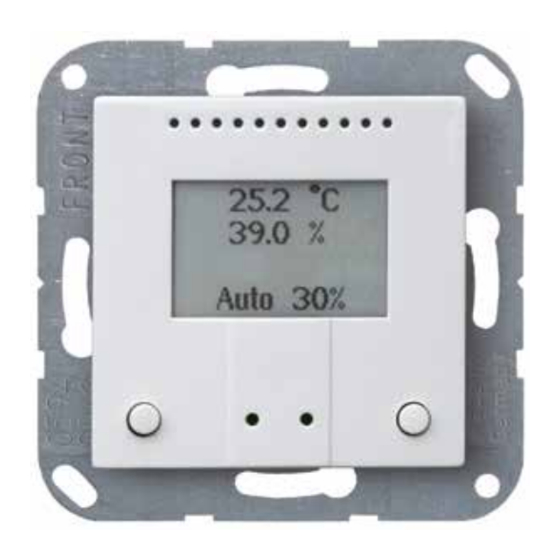
Use of the device, manual airing Use of the device, manual airing 5.1. Standard display The standard display page shows the current measuring values and the operating mode. • room temperature in °C 22.5°C 22.5°C • relative air humidity in % 45.4% 45.4% •... -
Page 26: Key Functions
In priority mode and when frost protection is activated, manual operation (and automatic mode) are blocked. Operation modes, page 29 5.2.1. Key functions The following applies for the integrated buttons of the TH PF-U and for the buttons/ actuators connected to the inputs: Window Ventilator speed... - Page 27 LEDs light up Priority mode It is possible to make a priority switch via the TH PF-U inputs: If a signal is issued for more than 3 seconds at an input, this command takes priority. Manual operation and automatic mode are blocked.
- Page 28 Elsner Elektronik GmbH Control and Automation Technology Sohlengrund 16 75395 Ostelsheim Phone +49(0)70 33/ 30945-0 info@elsner-elektronik.de Germany +49 (0) 70 33/ 30945-20 www.elsner-elektronik.de Technical support: +49 (0) 70 33 / 30 945-250...
Need help?
Do you have a question about the TH PF-U and is the answer not in the manual?
Questions and answers