
Related Manuals for Xantrex 817-1050

Summary of Contents for Xantrex 817-1050
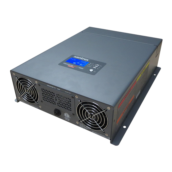
- Page 1 Owner’s Guide Freedom XC Series Inverter Charger Product Part Numbers 817-1050 817-2080...
- Page 3 _________________________________ Date and Revision Purchase Date _________________________________ June 2017 Rev A Product Part Number To view, download, or print the latest revision, visit the website shown under Contact Information. 817-1050 (Freedom XC 1000 120VAC) 817-2080 (Freedom XC 2000 120VAC) 975-0784-01-01...
- Page 4 Inverter. It also provides information Related Information about troubleshooting the unit. It does not provide details about particular You can find more information about Xantrex products and services at brands of batteries. You need to consult individual battery manufacturers http://www.xantrex.com.
-
Page 5: Important Safety Instructions
Important Safety Instructions DANGER IMPORTANT: R ’ EAD AND SAVE THIS WNER UIDE DANGER indicates an imminently hazardous situation, which, if not FOR FUTURE REFERENCE avoided, will result in death or serious injury. This guide contains important safety instructions for the Freedom XC WARNING Series Inverter Charger that must be followed during operation and troubleshooting. - Page 6 Safety Information Before using the Inverter, read all instructions and cautionary Do not expose this unit to rain, snow, or liquids of any type. This markings on the unit, the batteries, and all appropriate sections of product is designed for indoor use only. Damp environments will this manual.
- Page 7 DANGER WARNING HAZARD OF ELECTRIC SHOCK, EXPLOSION, OR ARC FIRE AND EXPLOSION HAZARD • Unit’s components may produce arcs or sparks. FLASH • Apply appropriate personal protective equipment (PPE) and follow • Do not install near batteries, in machinery space, or in an area in safe electrical work practices.
- Page 8 Freedom XC inverter products are designed for deep cycle lead-acid CAUTION batteries. See warning below when connecting to lithium ion batteries. Do not use transformerless battery chargers in conjunction with the ELECTRICAL SHOCK AND FIRE HAZARD inverter due to overheating. •...
- Page 9 Precautions When Working With Batteries Use extra caution to reduce the risk of dropping a metal tool on the battery. It could spark or short circuit the battery or other electrical parts and could cause an explosion. Use tools with insulated handles Battery work and maintenance must be done by qualified Important: only.
- Page 10 Precautions When Placing the Inverter Regulatory The Freedom XC Series Inverter Charger is certified to appropriate US and WARNING Canadian standards. For more information see “Regulatory Approvals” on page 73. FIRE HAZARD The Freedom XC Series Inverter Charger is intended to be used for mobile Do not install the inverter or any part of its supplied wiring in engine or commercial applications.
- Page 11 FCC Information to the User This equipment has been tested and found to comply with the limits for a Class B digital device, pursuant to part 15 of the FCC Rules. These limits are designed to provide reasonable protection against harmful interference in a residential installation.
-
Page 13: Table Of Contents
Contents Important Safety Instructions ..................iii Introduction . -
Page 15: Introduction
DC cables (not shown) Product image shown may vary from actual product. NOTE: If any of the items are missing, contact Xantrex or any authorized Xantrex dealer for replacement. See “Contact Information” on page i. Owner’s Guide and extra labels Figure 1 What’s In The Box... - Page 16 Introduction Key Features Power for Most Appliances The Freedom XC inverter/charger • Low Voltage Shutdown Delay Timer: Configurable from provides up to 1000 watts (Freedom XC 1000) or 2000 watts 1 to 300 seconds to reduce an unnecessary shutdown of (Freedom XC 2000) of continuous utility grade, sine wave power inverter operation such as during cranking or other brief derived from a battery bank.
- Page 17 Introduction Over temperature Alarm and Shutdown During Battery Mode, • Ignition Lockout: The Freedom XC features the ability to the Freedom XC automatically alerts you if it is overheating and inhibit the inverter from operating in the absence of a approaching the over-temperature shutdown limit.
-
Page 18: Features
Features AC and DC Panel Feature Description Remote port allows you to connect an accessory remote control device. ACC input terminal for connecting ignition control wiring. Ignition Control Switch (ACC) for connecting [ON (|)] and disconnecting [OFF (O)] the ignition signal. AC output knockout can be removed for routing AC output wiring. - Page 19 Features GFCI Panel Feature Description GFCI cover is removed when installing a GFCI outlet. Location of GFCI receptacles. 20 A supplementary protector with reset button provides overload protection for the Freedom XC GFCI kit (PN: 808-9817). Press to recover from an overload condition.
- Page 20 Features Display Panel Feature Description Display panel displays status information on the screen. It is comprised of a display screen, LEDs, select and power buttons. INPUTBATTTEMP OUTPUTBATTLOAD ERROR BYPASS OVERLOAD 100% CHARGING Multi-function LCD screen shows status information and error codes. Status LEDs indicate the mode of operation.
- Page 21 Features Side Panel Feature Description Captive nut panel screw holds the wiring compartment cover in place. Wiring compartment cover protects the wiring compartment from debris and keeps the cables secure. Using the captive nut panel screw, the cover can be opened and lifted out during wiring.
-
Page 23: Safety Instructions
Safety Instructions Before You Begin the Installation Installation Codes Before beginning your installation: Governing installation codes vary depending on the specific location and application of the installation. Some examples include • Read this entire Installation section so you can plan the the following: installation from beginning to end. -
Page 24: Installation Tools And Materials
Installation Tools and Materials You will need the following to install the Freedom XC: ❐ Wire stripper ❐ Mounting (#2) screws or bolts ❐ #2 Phillips screwdriver ❐ 3mm slot long neck screwdriver for spring clamp AC terminals ❐ Wrench for DC terminals (½" or 13mm socket wrench) ❐... -
Page 25: Basic Installation Procedures
Basic Installation Procedures This section provides sample installation information as a guide for your installation. For your convenience, the overall procedure is divided into these main steps: ❐ Step 1: Designing the Installation on page 12 ❐ Step 2: Choosing a Location for the Unit on page 17 ❐... -
Page 26: Step 1: Designing The Installation
Basic Installation Procedures Step 1: Designing the Installation Most Freedom XC installations share common components, and some of these are briefly described in Figure 1. Equipment Ground Figure 1 shows some components and their relationship to each other in a typical recreational vehicle or fleet vehicle installation. Also, see “Marine Installation”... - Page 27 Basic Installation Procedures AC Shore Power XC input must be sized adequately to carry current up to the rating of the input breaker and in accordance with the electrical codes or A source of 120 volts AC 60Hz sine wave alternating current regulations applicable to your installation.
- Page 28 Basic Installation Procedures AC Cabling AC Distribution Panels AC cabling includes all the wires and connectors between the AC Most systems incorporate distribution centers both ahead of the source and the Freedom XC, as well as all cabling between the Freedom XC (the AC source panel) and between the Freedom XC Freedom XC and the AC output panels, circuit breakers, and loads.
- Page 29 Basic Installation Procedures AC Output Neutral Bonding DC Cabling The neutral conductor of the Freedom XC’s AC output circuit (that This includes all the cables and connectors between the batteries, is, AC Output Neutral) is automatically connected to the safety the DC disconnect and over-current protection device, and the ground during inverter operation.
- Page 30 Basic Installation Procedures Batteries Important: Using the correct cable size is critical to achieving the rated performance of the Freedom XC unit. When starting a heavy load the The Freedom XC uses 12-volt battery banks. Every Freedom XC Freedom XC can draw current surges from the battery of up to 400A. If the system is recommended to have a deep-cycle battery or group of DC wiring is too small the voltage drop from this surge will result in a batteries with a total capacity of 100 Ah or more which provides the...
-
Page 31: Step 2: Choosing A Location For The Unit
Basic Installation Procedures Step 2: Choosing a Location for the Unit inches at the AC end. The more clearance for ventilation WARNING around the unit, the better the performance. Do not allow the ventilation openings on the ends of the unit to become FIRE AND EXPLOSION HAZARDS obstructed. -
Page 32: Step 3: Mounting The Unit
Basic Installation Procedures Step 3: Mounting the Unit To mount the Freedom XC: See page 36 for drip Remove the Freedom XC from its shipping container, verify shield installation on Marine applications. that all components are present, and record relevant product information on “Information About Your System”... - Page 33 Basic Installation Procedures Connecting the Equipment Ground Grounding Locations You must connect the equipment ground lug to a grounding point— WARNING usually the vehicle’s chassis or DC negative bus ground—using recommended copper wire (if insulated then green insulation with FIRE HAZARD or without one or more yellow stripes) or larger.
-
Page 34: Step 4: Connecting The Ac Input Wires
Basic Installation Procedures Step 4: Connecting the AC Input Wires General AC Wiring Considerations WARNING AC Wiring Connectors Where applicable, connect AC wires FIRE, SHOCK, AND ENERGY HAZARDS with crimp-on splice connectors. The amount of insulation you strip Make sure wiring is disconnected from all electrical sources before off individual wires will be specified by the connector manufacturer handling. - Page 35 Basic Installation Procedures Table 5 Color codes for typical AC wiring Table 4 Required AC wire size vs. required breaker rating Color AC Wire Required Breaker Size (amps) Required Wire Size Green/yellow or bare copper Ground (Earth) Freedom XC (both 30 A maximum 10 AWG models)
- Page 36 Basic Installation Procedures AC Input Connections Ensure AC and DC power sources are turned off. 10mm AC Input knockout Install the required circuit breaker in the AC distribution panel NOTE: install a strain relief clamp (not shown) supplying AC power to the unit. •...
- Page 37 Basic Installation Procedures Using a 3mm slot long neck screwdriver, open the spring clamp by inserting the tool in the clamp slot and gently pulling the screwdriver handle forward, for Line terminal. Insert Line AC wire into Line (L) terminal slot on the unit. 10.
-
Page 38: Step 5: Connecting Ac Output To An Existing Ac Circuit
Basic Installation Procedures Step 5: Connecting AC Output to an Existing AC Circuit A manufacturer-tested and approved GFCI must be connected to the WARNING Freedom XC AC output, and GFCI protection must be provided on every receptacle connected to the AC hard wired installation. Other FIRE, SHOCK, AND ENERGY HAZARDS types may fail to operate properly when connected to the Freedom Make sure wiring is disconnected from all electrical sources before... - Page 39 Basic Installation Procedures AC Output Connections To make a permanent connection to existing AC wiring: Strip a single AC output wire, as appropriate. Remove the knockout and install a ½" strain relief clamp. 10mm AC Output knockout Route the wires through the strain relief clamp (not shown in NOTE: install a strain relief clamp (not shown) the figure).
-
Page 40: Step 6: Connecting The Dc Cables
Basic Installation Procedures Step 6: Connecting the DC Cables If at all possible, minimize routing your DC cables through an electrical distribution panel, battery isolator, or other device that NOTICE will cause additional voltage drops which can degrade the inverter’s REVERSE POLARITY DAMAGE ability to operate the loads. - Page 41 Basic Installation Procedures To make the DC connections Attach the cable lug that will join the cable to the inverter DC terminal. Cover the lug stem with heat shrink insulation (see Refer to Figure 5. Figure 5) to ensure that the lug does not touch the enclosure. Make sure the inverter is off and no AC or DC is connected to Install a fuse and fuse holder in the cable that will be used for the unit.
- Page 42 Basic Installation Procedures NOTICE enclosure outline (DC compartment side view) DC knockout EQUIPMENT DAMAGE hole Tighten the nuts on terminals properly. Loose connections cause excessive voltage drop and may cause overheated wires and melted insulation. DC terminal nut Do not over-tighten the nut on the DC input terminals. Damage to the DC input terminals may result.
- Page 43 Basic Installation Procedures DC Grounding WARNING To connect the DC ground: FIRE HAZARD The equipment grounding lug on the DC end of the Freedom XC is Do not complete the next step if flammable fumes are present. Explosion used to connect the chassis of the Freedom XC to your system’s DC or fire may result if the disconnect/battery selector switch is not in the off negative connection or grounding bus point as required by electrical position.
- Page 44 Basic Installation Procedures Connecting to ACC Signal The Freedom XC can be wired to inhibit inverter operation in the absence of a vehicle’s (or vessel's) ignition control signal. This feature can avoid unnecessary battery drain that would otherwise occur if the inverter was operated without a charging source such as the vehicle alternator.
- Page 45 Basic Installation Procedures Description of Ignition Control Features For information about the features and instructions on changing the ignition control features, see “Inverter and Charger Operation” on page 39. Ignition Auto- This setting allows the inverter to operate (Battery mode) automatically when an ignition control wire is on () connected to the ACC input and a valid ignition signal is constantly detected.
-
Page 46: Step 7: Connecting To A Remote Panel
Basic Installation Procedures Step 7: Connecting to a Remote Panel To connect the remote panel: ◆ Plug the Freedom X Remote panel (PN: 808-0817) to the RJ12 Remote port on the unit. NOTE: When the remote panel is connected, turn the inverter’s power button to the OFF position. -
Page 47: Step 8: Testing Your Installation
Basic Installation Procedures Step 8: Testing Your Installation Testing in Battery Mode WARNING To test the Freedom XC in invert mode: ELECTRICAL SHOCK HAZARD For hard wired installations, ensure shore power is not present. Pressing the Power button to turn OFF the Freedom XC inverter function Press the Power button to turn the inverter on. - Page 48 Basic Installation Procedures Testing in Grid Mode In the event of low or no battery voltage, shore power will NOTE: To test the Freedom XC in shore power mode: pass through the Freedom XC to the output even when shore ◆...
-
Page 49: Marine Installation
Marine Installation Figure 7 illustrates a typical marine installation with the following components: AC power supplied from a shore power connector An AC source panel that includes a max 30A (or a 15A if using a GFCI) circuit breaker that supplies the Freedom XC An AC load panel with branch circuit breakers that supply only loads that run off the Freedom XC Engine negative bus / DC ground bus... - Page 50 Marine Installation Drip Shield Installation The drip shields help to protect the unit from dripping or splashing Different Views liquids, which will cause a shock hazard when moisture comes in contact with electrical circuits in the unit. The drip shields are especially useful in marine installations where water from condensation, rain, or sea may come into contact with the Freedom WARNING...
- Page 51 Marine Installation To install the drip shields: Gather the four screws needed to fasten a single drip shield to a wall. Locate an appropriate setting for the drip shields above the Freedom XC making sure you cover the entire width of the unit....
-
Page 53: Inverter And Charger Operation
Inverter and Charger Operation Freedom XC Display Panel Status LED Indicators Indicator Definition Status LED indicators Indicates grid mode in which shore power is solid green available and passing through to the loads and charging the battery. Indicates Battery mode (Inverter mode) in INPUTBATTTEMP OUTPUTBATTLOAD Function buttons... - Page 54 Inverter and Charger Operation Function Buttons LCD Screen The LCD Screen changes depending on the operating mode of the Button Definition inverter. return to default screen or exit setting mode AC IN or AC OUT indicator next screen or next selection left LCD display middle LCD right LCD...
- Page 55 Inverter and Charger Operation LCD Screen Icons Icon Definition The load icon is displayed if there is voltage available Icon Definition at the AC output. AC input and output indicator. The wrench icon underneath a number is displayed The bar represents load consumption levels. 100% is during configuration mode.
-
Page 56: Viewing Information During Battery Mode
Viewing Information During Battery Mode The LCD screen displays information related to battery mode Info and Setting LCD Screen operation. Screen 3 of 4 - ◆ Press the Scroll button to move from screen to screen. INPUTBATTTEMP OUTPUTBATTLOAD ... -
Page 57: Viewing Information During Grid Mode
Viewing Information During Grid Mode The LCD screen displays information related to AC bypass or Info and Setting LCD Screen charger operation. Press the Scroll button to move from screen to screen. Screen 1 of 5 - BATT BATT ... - Page 58 Viewing Information During Grid Mode Info and Setting LCD Screen Info and Setting LCD Screen Screen 2 of 5 - Screen 4 of 5 - INPUT LOAD BATT BATT Battery Voltage/ AC input voltage/ Charging Current AC input frequency...
-
Page 59: Adjusting Feature Settings In Configuration Mode
Adjusting Feature Settings in Configuration Mode , Scroll , and buttons can be used to cycle through the various feature settings: Press and hold the button for three seconds to enter the feature settings mode. Press the Scroll button to move through the different feature settings. - Page 60 Adjusting Feature Settings in Configuration Mode Settings Setting Default Range of Setting Name Number Value Values Description Inverter Ignition Control , , See “Description of Ignition Control Features” on page 31. LBCO Voltage . . to . The voltage setting value can be adjusted by 0.1 increments.
- Page 61 Adjusting Feature Settings in Configuration Mode Setting Default Range of Setting Name Number Value Values Description Inverter Output Power . to . The wattage setting value can be adjusted by 100-watt increments. Use Limit (Freedom XC 1000) with Inverter Output Power Limit Timer especially when pairing with a lithium ion battery.
- Page 62 Adjusting Feature Settings in Configuration Mode Setting Default Range of Setting Name Number Value Values Description Battery Type (Flooded), (AGM), (Gel), (Custom) Battery Temperature (Cold), Selecting Cold from Warm will increase charger voltage by 0.4V. ...
- Page 63 Adjusting Feature Settings in Configuration Mode To change the default value to a different value: Press and hold the button for three seconds to enter the feature settings mode. Press the Scroll button to move through the different feature settings. Press the button to select a setting number and change its value.
-
Page 64: Operating In Battery Mode
Operating in Battery Mode Turning Inverter Operation ON and OFF The Freedom XC is in Battery Mode (also called Inverter Mode) when all the following conditions exist: There are two ways to operate the Freedom XC’s inverter. • Press the Power button to a down position (it is Off in the up •... - Page 65 Operating in Battery Mode Power Save Timer Checking Battery Status The Power Save Timer is an adjustable countdown timer from 1 to During inverter operation (in battery mode), you can check the 25 hours (25 hours is the default) that automatically shuts down battery status by observing the battery capacity indicator on the inverter operation to reduce battery discharge and preserve battery LCD screen.
- Page 66 Operating in Battery Mode Turning the Audible Alarm ON or OFF The Freedom XC’s audible alarm can be muted. See “Adjusting Feature Settings in Configuration Mode” on page 45. Any warnings such as error or fault conditions or imminent shutdown are both displayed on the LCD screen and sounded on the alarm speakers.
-
Page 67: Operating In Grid Mode
Operating in Grid Mode Battery Charger Functions Battery Types When AC power is available, the Freedom XC can operate as a 12- Freedom XC charges flooded (or wet) lead-acid, Gel, AGM volt battery charger. Different battery types and chemistries require (absorbed glass mat), and custom batteries. - Page 68 Operating in Grid Mode 3-Stage Charging Algorithm Bulk Stage Absorption Stage Float Stage When enabled, the Freedom XC will charge batteries in a sequence Battery Voltage known as three-stage charging. Whenever qualified AC power is Absorption Voltage present at the inverter’s input, it passes power through to the Float Voltage 3-Stage Charge connected load and begins charging the batteries.
- Page 69 Operating in Grid Mode Bulk Stage The Freedom XC transitions to the float stage if either one of the following two conditions are met: Bulk charge is the first stage in the charging process and provides The charge current allowed by the batteries falls below the exit the batteries with a controlled, constant current.
- Page 70 Operating in Grid Mode Equalize Charging Table 7 Preset Float Voltage Settings Many battery manufacturers recommend periodic equalize charging Battery Type Preset Float Voltage to counter cell charge imbalance and capacity-robbing electrolyte Freedom XC 1000 stratification. Equalizing helps to improve battery performance and Flooded 13.5 lifespan by encouraging more of the battery material to become...
- Page 71 Operating in Grid Mode Custom Battery Settings Menu Bulk Stage Absorption Stage Equalize Stage Battery Voltage NOTICE Equalize Voltage Bulk Voltage Absorption Voltage EQUIPMENT DAMAGE 10% of charge current Equalize mode To avoid damaging your batteries during charging or equalization, Custom Charge consult your battery manufacturer and associated documentation before setting a custom battery type.
-
Page 72: Operating During Transition Between Grid Mode And Battery Mode
Operating During Transition Between Grid Mode and Battery Mode Transitioning from Grid Mode to Battery Mode The Freedom XC’s advanced power management is capable of transitioning power from an AC source to DC source within a When the unit is operating in grid mode and shore power is lost, the fraction of a second and vice-versa. - Page 73 Operating During Transition Between Grid Mode and Battery Mode Operating Limits Power Output Operating Battery Condition Voltage Comment The Freedom XC can deliver up to 1000 watts (Freedom XC 1000) Instant Low < 10.2 volts After two seconds below the limit, the unit shuts and 2000 watts (Freedom XC 2000) of continuous utility grade sine Voltage down inverter output completely.
- Page 74 Operating During Transition Between Grid Mode and Battery Mode Overload Conditions Over-temperature Conditions There are two kinds of overload conditions: During inverter operation, when the Freedom XC’s internal temperature starts to approach its preset shutdown limit, the display • an overload warning will show error code .
- Page 75 Operating During Transition Between Grid Mode and Battery Mode Routine Maintenance Freedom XC Unit Minimal maintenance is required to keep your Freedom XC operating properly. Periodically you should: • Clean the exterior of the unit with a damp cloth to prevent the accumulation of dust and dirt.
-
Page 77: Troubleshooting
Troubleshooting • Any known unusual AC shore power factors such as low WARNING voltage, unstable generator output, etc. • Whether any extreme ambient conditions existed at the ELECTRICAL SHOCK HAZARD time (temperature, vibrations, moisture, etc.) Do not disassemble the Freedom XC. It does not contain any user- If your Freedom XC is not displaying an error code, check the serviceable parts. -
Page 78: Warning Messages
Warning Messages Warning messages in the form of audible alarms and error codes The error codes are listed in Table 8 below. The text in the Error that appear on the LCD screen to alert you to an impending system Code column appears on the LCD screen of the display panel. - Page 79 Warning Messages Table 8 Error Codes Displayed on the LCD Screen Error Code Condition Mode Action Low battery voltage detected Battery mode (inverting) • Check battery status and recharge if necessary. depending on setting, see • Check for proper DC cable sizing. “Operating Limits”...
-
Page 80: Troubleshooting Reference
Troubleshooting Reference WARNING ELECTRICAL SHOCK HAZARD Do not disassemble the Freedom XC. It does not contain any user- serviceable parts. Attempting to service the unit yourself could result in an electrical shock or burn. Failure to follow these instructions can result in death or serious injury. NOTICE INVERTER DAMAGE Avoid continually overloading the inverter and subjecting it to... - Page 81 Troubleshooting Reference Table 9 Troubleshooting Reference Problem Possible Cause Solution No output voltage. The status LED is red. AC shore power is not available or out of operating range and the inverter has shut down with the LCD screen showing one of the following error codes: •...
- Page 82 Troubleshooting Reference Table 9 Troubleshooting Reference Problem Possible Cause Solution No output voltage is shown in the LCD GFCI (when installed) has tripped or Check load and reset the GFCI or supplementary breaker. screen but the green status LED for Battery supplementary breaker has tripped.
- Page 83 Troubleshooting Reference Table 9 Troubleshooting Reference Problem Possible Cause Solution The fan turns on and off during AC shore • The battery is discharged. Do not be alarmed, the unit is performing normally. power mode. • AC pass-through current is high. The fan turns on and off during inverter The inverter is running continuously at Do not be alarmed, the unit is performing normally.
-
Page 84: Inverter Applications
Inverter Applications Motor Loads The Freedom XC performs differently depending on the AC loads connected to it. If you are having problems with any of your loads, read this section. Induction motors (that is, motors without brushes) require two to six times their running current on start up. -
Page 85: Specifications
Specifications NOTE: Specifications are subject to change without prior notice. Physical Specifications Freedom XC 1000 Freedom XC 2000 L × W × H 14.2” (360mm) × 10.6” (270mm)× 3.7” (95mm) 15.4” (390mm) × 10.8” (275mm)× 4.0” (102mm) Net Weight 13.4 lbs (6.1 kg) 16.3 lbs (7.4 kg) Environmental Specifications Freedom XC 1000... - Page 86 Specifications DC Input (For Inverting) Freedom XC 1000 Freedom XC 2000 Operating voltage range LBCO voltage –18.0 VDC LBCO voltage –18.0 VDC Maximum non-operating voltage 24 VDC 24 VDC Nominal voltage 12.0 VDC 12.0 VDC Nominal current at full load 100 ADC 192 ADC AC Output (For Inverting)
- Page 87 Specifications AC Input (For Charging) Freedom XC 1000 Freedom XC 2000 Operating voltage range 85–140 VAC 85–140 VAC Safe non-operating voltage range up to 240 VAC up to 240 VAC Full load maximum current 7 Arms 11 Arms Nominal frequency 60 Hz 60 Hz Power factor at full charge...
- Page 90 Schneider Electric Solar Inverters USA Inc. +1 800 670 0707 +1 408 987 6030 http://www.xantrex.com 975-0784-01-01 Printed in China...
Need help?
Do you have a question about the 817-1050 and is the answer not in the manual?
Questions and answers