Table of Contents
Advertisement
Quick Links
Advertisement
Table of Contents

Summary of Contents for Ubiquiti mFi Outlet mFi-MPW-W
- Page 1 In-Wall Manageable Outlet Model: mFi-MPW-W...
-
Page 2: Package Contents
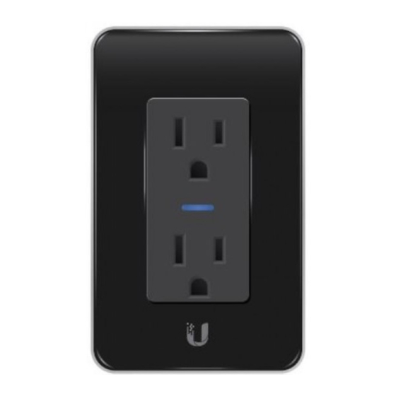
Introduction Thank you for purchasing the Ubiquiti Networks® mFi® Outlet, model mFi-MPW-W. The mFi Outlet is designed for integration with the mFi Controller software and features energy monitoring and configuration via Wi-Fi. This Quick Start Guide is designed to guide you through the hardware installation and software configuration. -
Page 3: Installation Requirements
Installation Requirements • Phillips screwdriver • Wire stripper/cutter • Needle-nose pliers (optional) IMPORTANT: The mFi Outlet is to be installed by a qualified electrician in accordance with local electrical codes and regulations. IMPORTANT: l’IFM est sortie pour être installé par un électricien qualifié, conformément aux codes électriques locaux et des règlements. -
Page 4: Wiring Overview
Wiring Overview Neutral (White) Ground (Green) 120V, 60 Hz Hot (Black) The mFi Outlet supports up to 15 amps per socket, with a total combined load of 15 amps. -
Page 5: Hardware Overview
Hardware Overview Status LED Reset Button Initialize Button Wall Plate Mounting Slots Interface Description The Status LED has four primary states: • Solid yellow When first powered on in factory default mode. • Flashing yellow Connecting to a Wi-Fi network. •... -
Page 6: Hardware Installation
Hardware Installation 1. Turn off power at the circuit breaker or fuse panel, and verify that the power is off. 2. Identify and label the wiring in the wall box. There should be two wires and a ground wire. Neutral Ground Electrical Outlet Wall Box Note:... - Page 7 3. Prepare the wiring in the wall box by stripping away 12 mm (½") of insulation from the end of each wire. 12 mm (½") 4. Connect the mFi Outlet wires to the wall box wires and secure each connection with a Wire Nut. a.
- Page 8 5. Bend and form the wires to fit into the wall box. Ensure the wires are properly positioned to allow adequate room for the mFi Outlet. 6. Place the mFi Outlet inside the wall box and ensure the yoke is mounted flush with the wall for proper fitting of the Wall Plate.
- Page 9 7. Mount the Wall Plate by aligning the mounting clips with the Wall Plate Mounting Slots on the mFi Outlet. Press the Wall Plate into position until the mounting clips snap into place. If you are using your own wall plate, secure it with two screws.
- Page 10 Configuring the mFi Outlet via Wi-Fi To configure the mFi Outlet, you must access it via Wi-Fi from a computer. The mFi Outlet has a default SSID (wireless network name) labeled mFi followed by the last six characters of the MAC address.
- Page 11 Accessing the Configuration Portal 1. Launch your web browser. Type https://192.168.2.20 in the address field. Press enter (PC) or return (Mac). 2. You may receive a security certificate warning. Click Proceed Anyway. 3. The Configuration Portal will appear. Select the wireless network name (SSID) of your existing wireless network from the drop-down list.
- Page 12 4. Enter your Wi-Fi security credentials. The options that appear are based on the encryption method used on your Wi-Fi network. 5. Enter your mFi Controller settings: • Address The IP address and http port used by the Controller. (The port is usually 6080, for example: 1.1.1.1:6080 or mfi.acme.com:6080) •...
- Page 13 8. If a Controller was specified, a flashing yellow checkmark will appear while the mFi Outlet is attempting to connect to the Controller. It will appear green once the mFi Outlet is connected. 9. Reconnect your computer to your wireless network by selecting the SSID from your wireless network utility.
-
Page 14: Specifications
Specifications mFi Outlet 110.8 x 71 x 67.7 mm Dimensions (4.32 x 2.8 x 2.67") 160 g Weight (without Wall Plate) (5.6 oz) Electrical Rating 15A, 110 - 125VAC, 50/60 Hz 15A per Socket (Not Simultaneous) Maximum Power Load 15A Total Combined Status LED Interface Reset Button... -
Page 15: Safety Notices
Safety Notices Read, follow, and keep these instructions. Heed all warnings. Only use attachments/accessories specified by the manufacturer. WARNING: Do not use this product in a location that can be submerged by water. AVERTISSEMENT : N’utilisez pas ce produit à l’emplacement qui peut être submergé... -
Page 16: Limited Warranty
Ubiquiti MAC label, or is missing any other original Ubiquiti label(s); or (VII) has not been received by Ubiquiti within 30 days of issuance of the RMA. In addition, the above warranty shall apply only if: the product has been properly installed and used at all times in accordance, and in all material respects, with the applicable Product documentation;... -
Page 17: Limitation Of Liability
SUBJECT TO LIMITATIONS, INTERRUPTIONS, DELAYS, CANCELLATIONS AND OTHER PROBLEMS INHERENT IN THE USE OF COMMUNICATIONS FACILITIES. UBIQUITI NETWORKS, ITS AFFILIATES AND ITS AND THEIR THIRD PARTY PROVIDERS ARE NOT RESPONSIBLE FOR ANY INTERRUPTIONS, DELAYS, CANCELLATIONS, DELIVERY FAILURES, DATA LOSS, CONTENT CORRUPTION, PACKET LOSS, OR OTHER DAMAGE RESULTING FROM ANY OF THE FOREGOING. - Page 18 Note Some countries, states and provinces do not allow exclusions of implied warranties or conditions, so the above exclusion may not apply to you. You may have other rights that vary from country to country, state to state, or province to province. Some countries, states and provinces do not allow the exclusion or limitation of liability for incidental or consequential damages, so the above limitation may not apply to you.
- Page 19 CAN ICES-3(B)/NMB-3(B) To reduce potential radio interference to other users, the antenna type and its gain should be so chosen that the equivalent isotropically radiated power (e.i.r.p.) is not more than that permitted for successful communication. This device complies with Industry Canada licence-exempt RSS standard(s). Operation is subject to the following two conditions: This device may not cause interference, and This device must accept any interference, including interference that...
- Page 20 RoHS/WEEE Compliance Statement English European Directive 2002/96/EC requires that the equipment bearing this symbol on the product and/or its packaging must not be disposed of with unsorted municipal waste. The symbol indicates that this product should be disposed of separately from regular household waste streams.
- Page 21 Español La Directiva 2002/96/CE de la UE exige que los equipos que lleven este símbolo en el propio aparato y/o en su embalaje no deben eliminarse junto con otros residuos urbanos no seleccionados. El símbolo indica que el producto en cuestión debe separarse de los residuos domésticos convencionales con vistas a su eliminación.
-
Page 22: Declaration Of Conformity
UBIQUITI NETWORKS device, megfelel a vonatkozó alapvetõ [Hungarian] követelményeknek és az 1999/5/EC irányelv egyéb elõírásainak. Íslenska Hér me l sir UBIQUITI NETWORKS yfir ví a UBIQUITI NETWORKS device, er í samræmi vi grunnkröfur og a rar kröfur, sem ger ar eru í [Icelandic] tilskipun 1999/5/EC. -
Page 23: Online Resources
Latviski Ar o UBIQUITI NETWORKS deklar , ka UBIQUITI NETWORKS device, atbilst Direkt vas 1999/5/EK b tiskaj m pras b m un citiem ar to saist [Latvian] tajiem noteikumiem. Lietuviškai UBIQUITI NETWORKS deklaruoja, kad šis UBIQUITI NETWORKS įrenginys atitinka esminius reikalavimus ir kitas 1999/5/EB [Lithuanian] Direktyvos nuostatas. - Page 24 . u b n t . c o m ©2013-2014 Ubiquiti Networks, Inc. All rights reserved. Ubiquiti, Ubiquiti Networks, the Ubiquiti U logo, the Ubiquiti beam logo, and mFi are trademarks or registered trademarks of Ubiquiti Networks, Inc. All other trademarks are the property of their respective owners.