Table of Contents
Advertisement
Quick Links
Advertisement
Table of Contents

Related Manuals for PARK AUDIO DF1408 MkII

Summary of Contents for PARK AUDIO DF1408 MkII
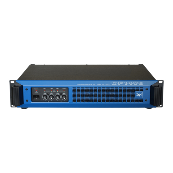
- Page 1 DF - series FOUR-CHANNEL PROFESSIONAL POWER AMPLIFIER DF1408 MkII OWNER'S MANUAL...
- Page 2 ACCESSORIES: 1. Power cord 2. Owner’s Manual 3. Warranty...
- Page 3 AVIS RISQUE DE CHOC ELECTRIQUE NE PAS OUVRIR CAUTION! The amplifier runs on 230V AC voltage. Removing the cover will expose you to a potentially dangerous voltage! Do not use the unit if the electrical power cord is frayed or broken. Power is supplied from 230 V AC single-phase grounded 50/60 Hz source! CAUTION! The amplifier can yield dangerous output voltage! Do not touch the non-...
- Page 4 GENERAL The DF1408 professional digital four-channel amplifier is designed for high MkII fidelity amplification of sound signals within a professional sound reproduction system. The amplifier can be operated in a four-channel mode, three-channel mode (one pair of channels bridged) or two-channel mode (both pairs of channels bridged). To ensure the most advantageous and faultless operation of the amplifier, please, read this Manual before use.
-
Page 5: Design Features
DESIGN FEATURES Physical Design The amplifier is enclosed in a metal (steel) case of 88 mm (2U) height. The amplifier is designed to be standard rack-mounted (RACK 19"). Physically, the amplifier consists of: • power supply unit; • four digital amplifying units installed on a common heat sink; •... - Page 6 making it possible to increase the power applied to the LF speaker without any danger of its overheating. The power of the amplifier is not wasted for cone flapping and allows the loudspeaker to achieve higher sound pressure. When it is necessary to achieve a linear frequency response to drive full-range loudspeakers generally used in studios or in cinema theatres, the input filter can be disabled (bypassed for each channel individually) with the slide switches located on the amplifier rear panel.
-
Page 7: Functional Features
FUNCTIONAL FEATURES Overload and Short-Circuit Protection Individual per each channel. This protective system becomes active in case of short- circuited output or overload caused by reduced load impedance. It disables the output signal of the respective channel for 0.5 second and then the amplifier gradually resumes its delivery. - Page 8 As soon as the amplifier cools down, the affected channels gradually regain their amplification level up to the set value. Soft Signal Start During the power-on process, this feature ensures smooth gain from zero to the maximum level to provide for a smooth rise of the sound level emitted from the loudspeakers.
-
Page 10: Front Panel
FRONT PANEL THERMAL – overheating alarm LED. Brightness depends on the temperature of the heat sink (See: Thermal Protection). POWER LED. When the DC output protection system becomes active it goes off irrespective of electric power applied to the amplifier. CLIP - overload alarm LEDs for Channels 1, 2, 3 and 4, respectively. -
Page 11: Rear Panel
REAR PANEL PROFESSIONAL POWER AMPLIFIER 230V 50/60Hz 1600VA max Serial No D8141010A000 THROUGH – line outputs for Channels 4, 3, 2 & 1, respectively (XLR male). Are used to deliver input signal along the respective channel to the input of another amplifier. - Page 12 OUTPUT – output SPEAKONs for Channels 1, 2, 3 and 4, respectively, used to connect to loudspeakes. To connect loudspeakers to Channels 1 & 2 and 3 & 4 functioning in the BRIDGE mode, use outputs for Channels 1 and 3, respectively. In addition, Channel 1 output connector is interlinked with Channel 2 output, while Channel 3 output connector with Channel 4 output, thus making it possible to use a single NL4FC connector (wired accordingly) to connect Channel 1 and 2...
-
Page 13: Cable Requirements
CABLE REQUIREMENTS Input Cables Make sure to use only shielded cables whether balanced or unbalanced. Shielding when properly grounded protects a signal against external electrical interference. As a rule, unbalanced lines over 3 meters long are not acceptable. Greater distances require a balanced cable. -
Page 14: Rack-Mounting Requirements
RACK-MOUNTING REQUIREMENTS The amplifier is designed to fit a standard 19” rack. While mounting, make sure to provide unhindered air access to the front and rear sides of the rack. Fan direction is from front to back. It is not necessary to leave empty space above or below the amplifier. For stationary use, it will be enough to fix securely only the front panel of the amplifier to the rack. -
Page 15: Input And Output Connectors
INPUT AND OUTPUT CONNECTORS Input Connectors Use XLR (male) connectors to connect to the amplifier inputs and XLR (female) connectors to line outputs. See the wiring on the figures below. XLR female XLR male Cold (–) Cold (–) Shield (Ground) Hot (+) Hot (+) Shield (Ground) -
Page 16: Operating Modes
OPERATING MODES Four-Channel Mode for Four Individual Signal Sources STEREO mode is used for both pairs of the channels. To Input Signal Sources MODE CH 3-4 MODE CH 1-2 switch is set to switch is set to STEREO STEREO PROFESSIONAL POWER AMPLIFIER 230V 50/60Hz 1600VA max Serial No D8141010A000 To Speaker Systems... - Page 17 Four-Channel Mode for Two Signal Sources MONO mode is used for both pairs of the channels. To Input Signal Sources MODE CH 3-4 MODE CH 1-2 switch is set to switch is set to MONO MONO PROFESSIONAL POWER AMPLIFIER 230V 50/60Hz 1600VA max Serial No D8141010A000 To Speaker Systems Apply an input signal to the inputs of Channels 1 and 3.
- Page 18 Two-Channel Mode Both pairs of channels are bridged. To Input Signal Sources MODE CH 3-4 MODE CH 1-2 switch is set to switch is set to BRIDGE BRIDGE PROFESSIONAL POWER AMPLIFIER 230V 50/60Hz 1600VA max Serial No D8141010A000 To Speaker Systems Apply an input signal to the inputs of Channels 1and 3.
- Page 19 Three-Channel Mode (Option 1) Using the bridge mode for one pair of channels and the individual mode for the other.* To Input Signal Sources MODE CH 1-2 MODE CH 3-4 switch is set to switch is set to STEREO BRIDGE PROFESSIONAL POWER AMPLIFIER 230V 50/60Hz 1600VA max Serial No D8141010A000...
- Page 20 Three-Channel Mode (Option 2) Using the bridge mode for one pair of channels and the individual mode for the other.* To Input Signal Sources MODE CH 3-4 MODE CH 1-2 switch is set to switch is set to MONO BRIDGE PROFESSIONAL POWER AMPLIFIER 230V 50/60Hz 1600VA max Serial No D8141010A000...
-
Page 21: Troubleshooting
TROUBLESHOOTING No Sound Signal on the Amplifier’s Output POWER LED is OFF: – damaged power cable; – no power; – DC protection mode. But for POWER LED all other LEDs are OFF: – no input signal; – input level attenuators are set to minimum position. SIGNAL and CLIP LEDs are occasionally blinking: –... -
Page 22: Specifications
SPECIFICATIONS Output Power: 350 W (channel into 8 Ohm, ~230 V) 700 W (bridge into 16 Ohm, ~230 V) * Peak Output Power: 420 W (channel into 8 Ohm, 10 ms, ~230 V) 840 W (bridge into 16 Ohm, 10 ms, ~230 V)* Frequency Response**: 20 Hz –... - Page 23 DIMENSIONS 445 max...
- Page 24 PARK AUDIO II, Ltd. Vinnytsia, Ukraine www.parkaudio2.com e-mail: park@parkaudio2.com Printed in Ukraine...