
Summary of Contents for KYORITSU KEW 1012
- Page 1 取扱説明書 INSTRUCTION MANUAL オートレンジ デジタル マルチメータ・AUTO RANGE DIGITAL MULTIMETER KEW 1012 KYORITSU ELECTRICAL INSTRUMENTS WORKS,LTD.,...
-
Page 2: Safety Warnings
This instruction manual contains warnings and safety rules which must be observed by the user to ensure safe operation of the instrument and retain it in safe condition. Therefore, read through these operating instructions before using the instrument. WARNING ● Read through and understand instructions contained in this manual before starting using the instrument. ● Save and keep the manual handy to enable quick reference whenever necessary. ● This instrument should only be used by suitably trained person and be sure to follow measurement procedures described in the manual. Kyoritsu assumes no responsibility for damage and injury caused by misuse or not following instructions in the manual. ● Be sure to understand and follow all safety instructions contained in the manual. Be sure to observe the above instructions. Failure to follow the above instructions may cause injury, instrument damage and/or damage to equipment under test. -
Page 3: Specification
CAUTION ● Always make sure to check the Function Selector Switch is setting to the appropriate range before starting measurement. ● Do not expose the instrument to the direct sun, high temperature and humidity or dewfall. ● When the instrument will note be in use for a long period, place it in storage after removing the batteries. ● Use a cloth dipped in water or neutral detergent for cleaning the instrument. Do not use abrasives or solvents. ● Allowable measurement time at 10A range of current function is 15 seconds. If you carry on making measurement continuously over 15 seconds, it can cause instrument damage. Please refer to following explanation of the symbols marked on the instrument or in the manual. Symbols ● Ground : : : AC and DC Resistance : Ω: Diode Buzzer : : Capacitor Frequency : Hz: Double or reinforced insulation F : Measurement category ● Primary electrical circuit of equipment with power cord for connection to outlet. CAT.Ⅱ: Primary electrical circuit of the equipment, which is supplied power from a distribution board, and cable run from a distribution board to an outlet. CAT.Ⅲ: 2. Features This instrument, KEW1012, is a Digital Multimeter which designed for making measurement of the low-voltage equipment. - Page 4 ±1.5%rdg±5dgt (50 / 60Hz) 6.000V ±1.8%rdg±5dgt (40〜400Hz) Overload protection: 600V DC or AC 0〜600V rms Impedance: 10MΩ 60.00V ±1.2%rdg±3dgt (50 / 60Hz) ACV (4 Auto ranging) 0.1V or less is outside the accuracy ±1.5%rdg±3dgt (40〜400Hz) 600.0V Crest factor(CF): 3.0 or less ±1.5%rdg±5dgt (50 / 60Hz) 600V ±1.8%rdg±5dgt (40〜400Hz) 600.0 μ A 0〜6000μA 6000 μ A (2 Auto ranging) Overload protection: 0.8A/600V ±1.2%rdg±3dgt 60.00mA 0〜600mA DCA (2 Auto ranging) 600.0mA 6.000A 0〜10A ±2.0%rdg±5dgt Overload protection: 10A/600V (2 Auto ranging) 10.00A 600.0 μ A 0〜6000μA 6000 μ...
- Page 5 ● Standards IEC61010-1 Measurement CAT.Ⅲ 300V, pollution degree 2 / Measurement CAT.Ⅱ 600V, pollution degree 2 IEC61010-031 IEC61326 ● Mode of operation △∑ mode ● Indication LCD maximum value 6000 (ACV/A, DCV/A, Ω) / maximum value 9999 (Hz) / maximum valve 4000 (F) , units, symbols ● Over range display "OL" symbol is displayed on the LCD. "OL" displayed when exceeding the measuring ranges. (except for AC/DC 600V ranges and AC/DC 10A ranges.) ● Auto-ranging Range shifts to upper range when indicated value is more than 6040. Range shifts to lower range when indicated value is less than 560. ● Sampling rate approx. 400ms ● Operating Environmental −indoor use conditions −altitude up to 2000m ● Temperature & Humidity range (guaranteed accuracy) 23℃±5℃ Relative humidity: less than 75% ● Operating Temperature & Humidity range 0℃〜+40℃ Relative humidity: less than 80% ●...
-
Page 6: Instrument Layout
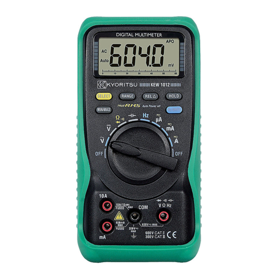
4. Instrument Layout ② ⑤ ⑥ ①Function Selector Switch ②Display ④ ⑦ ③MIN/MAX Key ④SELECT Key ③ ⑤RANGE Key ⑥REL Key ⑧ ① ⑦HOLD Key ⑧Hz/DUTY Key ⑬ ⑨Measuring terminal (V/Ω/Hz) ⑩Measuring terminal (COM) ⑪ ⑪Measuring terminal (10A) ⑫Measuring terminal (mA) ⑨ ⑬Test Leads ⑭Holster ⑫ ⑭ ⑩ 5. Preparation 5-1 Checking Battery Voltage Set the Function Selector Switch to other positions except the OFF position. Battery Voltage is enough if indication is clear and symbol is not indicated in this bout. +− symbol is indicated or no indication on the display, follow to the Battery. +− Replacement procedures shown in section 9 in this document and replace with new batteries. 6. Measurements 6-1 Voltage Measurement (DCV, ACV) DANGER ●... - Page 7 (2) Set the Function Selector Switch to " " position.(Then, "AC", "Auto", and "V" symbols are indicated on the display.) (3) Connect the test leads to the circuit under test. Measured value is indicated on the display. Note) When you make measurement of the voltage less than 0.1V at the AC6V range, the measurement value cannot be indicated correctly. Even if short-circuit the input line at the range of AC6V, 1〜3dgt may remain indicated. In that case, by pressing "REL" Key, "0" will be indicated. 6-2 Current Measurement (DCA/ACA) DANGER ● Do not apply voltage to the current measuring terminals. ● To avoid the danger of getting electrical shock, never make measurement on a circuit over 600V AC/DC. (electrical potential to ground 300V AC/DC) ● Do not operate the Function Selector Switch during measurement. ● Do not make measurement when opening the battery cover and the instrument case. 6-2-1 DC Current Measurement (up to 600mA) (1) Insert the black test lead plug into the COM terminal and the red test lead plug into the mA terminal. (2) Set the Function Selector Switch to the appropriate "uA" or "mA" position. In case that the measurement current is 6000uA or less, set the Function Selector Switch to "uA" position, and it is 600.0mA or less, set the Function Selector Switch to "mA" position.(Then, "DC" , "Auto", and "uA"or "mA" symbols are indicated on the display.) (3) Power off the circuit under test.
- Page 8 (5) Connect the test leads to the circuit under test so the instrument is in the series. (6) Power on the circuit under test. (7) Measured value is indicated on the display. 6-2-4 AC Current Measurement (up to 10A) CAUTION ● For safety sake, the measuring time on 10A range should be 15 seconds or less. Interval time between 2 measurements should be greater than 15 minutes. If you carry on making measurement continuously over 15 seconds, or make measurement in short interval time, it may cause error of measurement and instrument damage. (1) Insert the black test lead plug into the COM terminal and the red test lead plug into the 10A terminal. (2) Set the Function Selector Switch to "A" position.(Then, "DC" , "Auto", and "A" symbols are indicated on the display.) (3) Set the instrument to AC mode by pressing "SELECT" Key.(Then, "AC" symbol is indicated on the display.) (4) Power off the circuit under test. (5) Connect the test leads to the circuit under test so the instrument is in the series. (6) Power on the circuit under test. (7) Measured value is indicated on the display. 6-3 Resistance Measurement (Ω/ Diode check/ Continuity Check) DANGER ●...
- Page 9 (Then, " " and "Ω" symbols are indicated on the display.) Make sure that the "OL." symbol is indicated on the display at this bout, then short the test lead tips and check "0" is indicated on the display and check if the buzzer beeps. (4) Connect the test leads to both ends of the resistance under test. Measured value is indicated on the display. The buzzer beeps below about 100Ω. Note) Even if short the test lead tips, indicated value may not be "0". But this is because of the resistance of test leads and not a failure. In that case, by pressing "REL" key, "0" will be indicated. 6-4 Capacitance Measurement DANGER ● To avoid the danger of getting electrical shock, never make measurement of the circuit in which electric potential exists. ● Do not make measurement when opening the battery cover and the instrument case. ● Make sure to discharge the capacitor before making measurement. (1) Insert the black test lead plug into the COM terminal and the red test lead plug into the VΩHz terminal. (2) Set the Function Selector Switch to " " position.(Then, "Auto" and "nF" symbols are indicated on the display.) (3) Press the "REL" key and "0" shall be indicated.(Then, "△" symbol is indicated on the display.) (4) Connect the test leads to both ends of the Capacitance under test. Measured value is indicated on the display. Measuring unit "nF" / "uF" is automatically chosen and indicated due to the measured value. Note) It may take some time according to the measuring capacitance. Measuring capacitance < 4uF ---------- Measuring time is about 2seconds Measuring capacitance < 40uF ---------- Measuring time is about 7seconds Measuring capacitance < 100uF ---------- Measuring time is about 15seconds 6-5 Frequency Measurement DANGER ● To avoid the danger of getting electrical shocks, never make measurement on a circuit over 600V AC/DC. (electrical potential to ground 300V AC/DC) ● Do not operate the Function Selector Switch during measurement. ● Do not make measurement when opening the battery cover and the instrument case. (1) Insert the black test lead plug into COM terminal and the red test lead plug into the VΩHz terminal. (2) Set the Function Selector Switch to "Hz" position.(Then, "Auto" and "Hz" symbols are indicated on the display.) (3) Connect the test leads to the circuit under test. Measured value is indicated on the display. Frequency can be measured at ACV and ACA functions by pressing "Hz/DUTY" key. Concerning with the direction for use of "Hz/ DUTY" key, please reference to the section 7-6 Hz/DUTY in this document.
- Page 10 7. How to use Function Switches 7-1 SELECT Key This key is to chose the measuring function at Ω/ Diode Check/ Continuity/ function and Current function(uA, mA, A). Actions at each function are as below. ● Ω/ Diode Check/ Continuity function When setting the instrument to "Ω/ Diode Check/ Continuity" function, "Ω"measuring mode has been selected in the initial condition. By pressing "SELECT" Key, measuring mode changes. "Ω" → "Continuity Check" → "Diode Check" ● Current function (uA, mA, A) When setting the instrument to any function of the "uA", "mA", and "A", DC Current Measuring mode has been selected in the initial condition. By pressing "SELECT" Key, measuring mode changes. "DC" → "AC" 7-2 MIN/MAX Key Press the "MIN/MAX" Key to lock MAX or MIN value, and the "MAX or MIN" sign will appear on the display, press it over 2 seconds to exit. It cannot display bar graph on MAX/MIN HOLD mode. 7-3 RANGE Key At each "ACV", "DCV", "Ω", "uA", "mA" and "A" function, setting for the measuring ranges can be done manually by pressing "RANGE" Key. ("Auto" symbol disappears from the display.) Every time when pressing "RANGE" Key, range moves. In order to change from manual mode to Auto-ranging, there are following 2ways. 1) Press "RANGE" Key for 2seconds 2) Change to the other functions. 7-4 REL Key The difference between measured values can be indicated on the display at each "ACV", "DCV", "Ω", "Capacitance", "ACA" and "DCA" function. When pressing "REL" Key, "△"symbol lights up and the value under measuring is stored. After that, the difference between stored value and measuring value is indicated on the display. It can be released by pressing the "REL" Key again, changing to the other functions. Note) Do not press "REL" Key over 2 seconds to cause the malfunction. It can be released again by pressing "REL"Key over 2 seconds. 7-5 HOLD Key The measured value can be hold at all functions. By pressing "HOLD" Key, "DH" symbol indicated on the display and the indicated value can be held. By pressing "HOLD" Key again, "DH" symbol disappears from the display and held data is released. 7-6 Hz/DUTY Key Making measurement for frequency of input signal and DUTY(Pulse width / Pulse period).
-
Page 11: Auto Power Off
8. Auto Power Off Auto power off function operates when about 15minutes passed after power on this instrument. When Auto power off function operates and the instrument powered off, the power-off statue returns to normal by pressing any key. And it is possible to release the Auto power off function. Turn the Function Selector Switch from OFF position to the function you want with pressing "SELECT" Key, and power on the instrument. 9. Battery & Fuse Replacement DANGER ● Never open the battery cover and the instrument case when making measurement. ● To avoid getting electrical shock, be sure to remove test leads from the instrument when opening the battery cover in order to replace batteries and fuses. 9-1 Battery replacement Screw (1) Remove test leads from the instrument. (2) Remove the holster from the instrument. (3) Loosen one screw on the bottom of the Instrument and open the battery cover then replace batteries. Battery : Two R6P(AA)1.5V or equivalent 9-2 Fuse replacement (1) Remove test leads from the instrument. (2) Remove the holster from the instrument. (3) Loosen two screws on the bottom of the instrument and open the battery cover, then replace fuses. Screw Fuse : F 600V/10A (Fast action type) φ6.3 x 32mm F 600V/800mA (Fast action type) φ6.3 x 32mm 10. Maintenance Use a cloth dipped in water or neutral detergent for cleaning the instrument. Do not use abrasives or solvents. ― 21 ―... - Page 12 保 証 書 DISTRIBUTOR KEW 1012 製造番号 保証期間 ご購入日 ( 年 月 日) より1カ年間 共立製品をお買い上げいただきありがとうございます。 保証期間内に通常のお取扱いで万一故障が生じた場合は、 保証規定により無償で修理いたします。 本書を添付の上ご依頼ください。 お名前 ご住所 〒 お電話番号 ( )−( )−( ) ◎保証規定をよくお読みください。 Kyoritsu reserves the rights to change specifications or Designs described in ◎本保証書は日本国内でのみ有効です。 this manual without notice and without obligations. ◎本保証書の再発行はいたしかねますので、大切に保管してくだ さい。 販売店名 92‑1825C...
Need help?
Do you have a question about the KEW 1012 and is the answer not in the manual?
Questions and answers