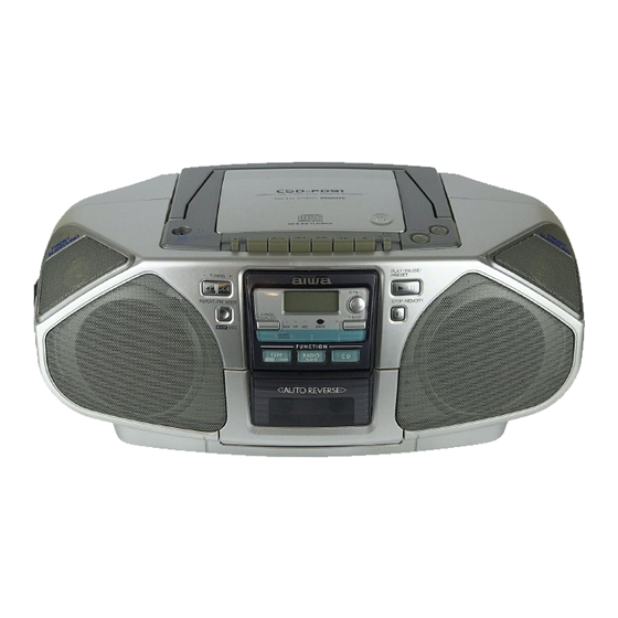
Aiwa CSD-FD91 Service Manual
100 mm cone type (2), 36 mm cone type (2) speakers
Hide thumbs
Also See for CSD-FD91:
- Operating instructions manual (10 pages) ,
- Service manual (6 pages) ,
- Service manual (15 pages)
Table of Contents
Advertisement
Quick Links
SERVICE MANUAL
COMPACT DISC STEREO RADIO
CASSETTE RECORDER
• This Service Manual is the "Revision Publishing" and replaces "Simple Manual",
(S/M Code No. 09-001-426-8T1).
• If requiring information about the CD mechanism, see Service Manual
of CMS-B31TG6, (S/M Code No. 09-001-341-1N2).
CSD-FD91
BASIC TAPE MECHANISM : TN-51RV-240
BASIC CD MECHANISM : CMS-B31TG6
S/M Code No. 09-003-426-8R1
U
Advertisement
Table of Contents

Related Manuals for Aiwa CSD-FD91


Summary of Contents for Aiwa CSD-FD91
- Page 1 CSD-FD91 SERVICE MANUAL COMPACT DISC STEREO RADIO BASIC TAPE MECHANISM : TN-51RV-240 CASSETTE RECORDER BASIC CD MECHANISM : CMS-B31TG6 • This Service Manual is the "Revision Publishing" and replaces "Simple Manual", (S/M Code No. 09-001-426-8T1). • If requiring information about the CD mechanism, see Service Manual of CMS-B31TG6, (S/M Code No.
-
Page 2: Specifications
SPECIFICATIONS Tuner section General Frequency range Speaker 100 mm cone type (2), 36 mm cone type (2) FM : 87.5 MHz–108 MHz Output Headphones jack (stereo mini-jack) Antenna : Rod antenna Power output 2.5 W + 2.5 W (EIAJ 7 ohms DC) AM : 530/531 kHz–1,710/1,602 kHz Power requirements... -
Page 3: Protection Of Eyes From Laser Beam During Servicing
PROTECTION OF EYES FROM LASER BEAM DURING SERVICING This set employs laser. Therefore, be sure to follow carefully the CAUTION instructions below when servicing. Use of controls or adjustments or performance of procedures other than those specified herein may result in hazardous WARNING! radiation exposure. -
Page 4: Electrical Main Parts List
ELECTRICAL MAIN PARTS LIST REF. NO. PART NO. KANRI DESCRIPTION REF. NO. PART NO. KANRI DESCRIPTION C822 87-010-401-080 CAP, ELECT 1-50V C823 87-010-178-080 CHIP CAP 1000P 87-A21-550-010 IC,TA2149N C824 87-010-178-080 CHIP CAP 1000P 87-A21-185-040 C-IC,LC72121M C829 87-010-178-080 CHIP CAP 1000P 87-A21-064-010 IC,LA4227 C830... - Page 5 REF. NO. PART NO. KANRI DESCRIPTION REF. NO. PART NO. KANRI DESCRIPTION C426 87-A11-608-080 C-CAP,S 0.33-25 K B CNA205 8A-CD9-626-010 CONN ASSY,2P DOOR C428 87-010-197-080 CAP, CHIP 0.01 DM CNA303 8A-CH4-634-010 CONN ASSY, 2P S-SP.L C429 87-010-186-080 CAP,CHIP 4700P CNA304 8A-CH4-635-010 CONN ASSY, 2P S-SP.R C430...
- Page 6 REF. NO. PART NO. KANRI DESCRIPTION REF. NO. PART NO. KANRI DESCRIPTION 87-012-140-080 CAP 470P C276 87-016-280-080 CAP,E 3.3-50 M BP SME 87-010-178-080 CHIP CAP 1000P CN204 8A-CH4-687-010 CONN,4P V 2.5 87-010-197-080 CAP, CHIP 0.01 DM CNA203 8A-CD9-628-010 CONN ASSY,3P MA-HP 87-010-197-080 CAP, CHIP 0.01 DM CNA204...
-
Page 7: Transistor Illustration
TRANSISTOR ILLUSTRATION E C B B C E E C B 2SA933 2SB1370 2SA1296 2SA1162 2SC1740 2SC1815 2SC2712 2SC1740 2SC2714 DTC114TS DTC114TK DTC124XS DTC114YK DTC144EK E C B 2SA1318 CHIP RESISTOR PART CODE Chip Resistor Part Coding Figure Resistor Code Value of resistor Chip resistor Dimensions (mm) - Page 8 WIRING - 1 (MAIN/CD) - 8 -...
- Page 9 SCHEMATIC DIAGRAM- 1 (MAIN/ CD (1/2)/ H.P/ KEY/ SP/ BATT1/ BATT2) – 9 –...
- Page 10 SCHEMATIC DIAGRAM- 2 (CD (2/2)) FOCUS BIAS ADJUST – 10 –...
- Page 11 WIRING - 2 (FRONT/H.P/KEY/BATT1/BATT2/SP) - 11 -...
- Page 12 SCHEMATIC DIAGRAM - 3 (FRONT) – 12 –...
Need help?
Do you have a question about the CSD-FD91 and is the answer not in the manual?
Questions and answers