
Summary of Contents for Happy Industrial Corporation HCH series
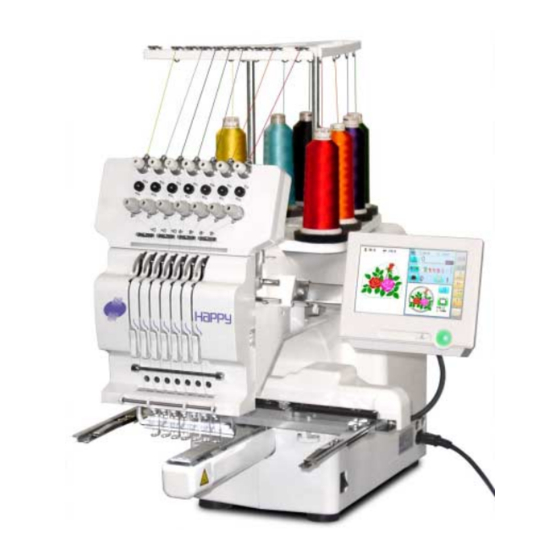
- Page 1 Computerized Compact Single Head Embroidery Machine INSTRUCTION BOOK Program Ver. *1.34 ~ Original instructions CHO512-13...
-
Page 3: Table Of Contents
INDEX How to select patterns from memory ..5-A IMPORTANT SAFETY INSTRUCTIONS .. 1-1 Erasing patterns from memory ....5-B WARNING LABELS & THEIR LOCATIONS ..1-2 NEEDLE BAR SELECTION ...... 5-E SETTING UP THE MACHINE SEWING WITH TUBULAR FRAMES Remove the machine from box.... - Page 4 INDEX Needle bar selection and Pattern settings... 17-4 PATTERN Registration of QUEUE setting ..... 17-6 Locking pattern data ......11-1 Trace type ..........11-2 Read QUEUE setting......17-7 Export ........... 11-3 OTHER SETTINGS Renaming patterns ....... 11-5 Create network ........18-1 Copying pattern data ......
-
Page 5: Important Safety Instructions
IMPORTANT SAFETY INSTRUCTIONS This electrical appliance is intended for household use. When using an electrical appliance, basic safety precautions should always be followed, includ- ing the following. Read all instructions before using this appliance. DANGER - To reduce the risk of electric shock: 1. -
Page 6: Warning Labels & Their Locations
WARNING LABELS & THEIR LOCATIONS Trapping, Puncture, Cut hazard wherever this label is found Injury risk on moving head(s) CAUTION Keep hands away from the moving heads while the Possibility of injury. machine is running. Keep hands away from the moving heads while the machine is running. -
Page 7: Setting Up The Machine
SETTING UP THE MACHINE We recommend unpacking should be done where it has enough room. CAUTION: To prevent accidents. The machine is quite heavy for one person to carry. Please use two persons when unpacking or carrying. Box (upper) CAUTION: To avoid problems. Make sure to hold bottom of the machine body when removing from the box. -
Page 8: Accessories
SETTING UP THE MACHINE Placement of Accessories Confirm all the accessories are contained when unpacking. Frame base CD-ROM (Instruction manual, Parts list) CD-ROM (Happy Link Software) Instruction manual Embroidery frame (Round) Embroidery frame (Square) Thread stand Thread guide bracket Carriage Thread stand felt (9 pcs) LAN cable USB cable... -
Page 11: Machine Installation
SETTING UP THE MACHINE Machine installation 1. Please use a stout table to set the machine Please check for any shaking or excessive vibrat- ing of the machine table when the machine is running. If you have a problem, Please use a stronger table for the machine. - Page 12 SETTING UP THE MACHINE 4. Please be sure you have this much room around your cap drive for it to move. Please machine on the table positioning like right side drawing. 0 ~ 10 mm 5. Please do not sit the machine near any kind of other electric equipment (Examples: Microwave or electric tool).
-
Page 13: Grounding Instruction
SETTING UP THE MACHINE GROUNDING INSTRUCTIONS (for type of 120V) This product must be grounded. In the event of malfunction or breakdown, grounding provides a path of least resistance for electric current to reduce the risk of electric shock. This product is equipped with a cord having an equipment-grounding conductor and a grounding plug. -
Page 14: Main Parts
MAIN PARTS 11. Minor thread tension 1. Hook cover 20. USB port 12. Thread guide support 2. Bobbin case (Standard-A receptacle) 13. Thread guide 3. Hook 21. LAN port 14. Upper rectifier 4. Needle plate 22. Frame base 15. Thread stand pin 5. - Page 15 MAIN PARTS CONTROL BOX 1. Display (L.C.D.) 5. USB port (Standard-A receptacle) 2. LAN port 6. USB port (Standard-B receptacle) 3. Thread cut button 7. Stylus 4. Start/Stop button BOBBIN WINDING 1. Upper Thread guide 2. Thread stand pin 3. Thread stand felt 4.
-
Page 16: The Control Box
THE CONTROL BOX CAUTION The touch screen can be operated by finger, but in some cases sensitivity of the screen will be affected by condition of the finger. In such cases, please use the fingertip or built-in stylus to hit small touch targets. Blinking red . - Page 17 DRIVE MODE Drive key The each key menu will be shown. Frame forward Needle change i-Custom Needle bar (default display) selection Drive speed Pressure foot Frame move Drive speed Low speed operation (OFF state) Press the button to turn "ON" state. Control embroidery speed.
- Page 18 DRIVE MODE Needle change When laser pointer is turned on, moving head moves to needle no.0 position and radiates. Pressure foot Change the needle bar directly to the indicated You can raise or lower the presser foot . needle number on the button. Change Jump (Off) The machine can embroider.
- Page 19 DRIVE MODE i-Custom 22-1 The following display and key icons are set as default. You can place other frequently used icons freely on the right side of Drive mode screen. Calendar When the key is pressed continuously, the "Key lock" function is activated and the frame will move Current year, month date is displayed.
- Page 20 3-6a DRIVE MODE Pointer (Option) Quick move Turn on and off the laser pointer. First press this key and then the arrow key to X Direction frame move move the frame toward the edge of the embroi- dery area in the direction of the arrow. YDirection frame move Quick embroidery design data position The frame can be moved with specified distance...
-
Page 21: Drive Mode
DRIVE MODE Speed setting by needle (ON state) Embroidery speed can be set by needle. If speed by needle exceeds the speed set at Drive speed setting, the value of speed turns gray and speed by the needle is applied to the speed set at Drive speed setting. You can be set up taking the following steps. - Page 22 DRIVE MODE Needle number and color Display example Mark for color change stop When beginning an embroidery Mark for frame out Name of selected pattern Stitches of pattern Memory # of selected pattern Size of pattern and distance Current *Color change Heigh number Width...
-
Page 23: Inserting A Needle
INSERTING A NEEDLE Select a needle of the right type. See the following “SELECT THREADS”. CAUTION: To prevent accidents. Turn off the power before removing the needle. 1. Loosen the needle clamp screw slightly with the screw- Needle clamp screw driver. -
Page 24: Select Needles And Threads
SELECT NEEDLES AND THREADS About needle Please select needles by type of material . Normally, We supply a DB X K5 needle as in the machine accessory kit. Relation of needle and upper thread Please select type of needle and upper thread by flowing list. k l i Normal em- broidery field... -
Page 25: Backing Materials
BACKING MATERIALS Backing Generally, Backing is used for hooped embroidery fabric. Knit fabrics particularly require the use of embroidery backings. Embroidery backings will allow the hoop to move the fabric more accurately, creating a more beautiful embroidery. Select backing type Choose the thickness and number of sheets by the type of material and embroidery condition. -
Page 26: Bobbin Winding
BOBBIN WINDING Winding the bobbin Thread the bobbin winder as shown below: 1. Upper Thread guide 2. Thread guide 3. Winder thread guide 4. Bobbin (Place the bobbin on the bobbin winder spindle.) 5. Press the limit lever as indicated by the arrow to start the winder. -
Page 27: Removing The Bobbin
BOBBIN WINDING CAUTION: To prevent accidents. Please watch out for the point of the rotary hook when you replace the bobbin. Removing the bobbin case 1. Open hook cover (A) to front. 2. Grasp bobbin case latch (B) and withdraw bobbin case from hook taking care not to damage the thread keeper. -
Page 28: Threading The Machine
THREADING THE MACHINE How to thread upper thread Pass upper threads in order according to the figure: Thread guide Upper rectifier Small cone Thread stand 1. Thread stand Set thread cone on the stand. Small cones can also be used as shown. 2. - Page 29 THREADING THE MACHINE 4. Minor thread tension 5. Guide pin upper 6. Detecting roller 7. Guide pin lower 8. Thread tension Wind upper threads one time around rotary tension disc clock-wise. 9. Upper thread guide 10.Lower thread guide 11.Lower rectifier 12.Thread adjusting spring 13.Take-up lever 14.Thread guide plate lower...
-
Page 30: How To Read These Instructions And Scrollbar4-8
HOW TO READ THESE INSTRUCTIONS and SCROLLBAR The instructions in this manual have been formatted as follows: Written instructions will be provided on the left side of the page while graphics depicting the necessary steps are provided on the right. Graphics on the far right will show the display after performing the steps indicated. -
Page 31: Displaying The Pattern In Setting Mode
DISPLAYING THE PATTERN IN SETTING MODE When there is shows on the right side menu, the pattern data may be shown on the screen. 1. When the machine is stopped, press 2. Select desired menu. Icon of will be shown in sub-menu. 3. -
Page 32: Turning The Machine On How To Turn On The Machine
TURNING THE MACHINE ON How to turn on the machine CAUTION The touch screen can be operated by finger, but in some cases sensitivity of the screen will be affected by condition of the finger. In such cases, please use the fingertip or built-in stylus to hit small touch targets. - Page 33 5-1b TURNING THE MACHINE ON 5. Select the desired frame with : Tubular round frame : Tubular square frame : Cap and One-point frame. : Border frame (for HCD2) : Sock frame : User-defined frame : Non registered 6. Select desired type of frame and Press The display returns to the view of Step 3.
-
Page 34: Calendar And Clock Setting
TURNING THE MACHINE ON Calendar and clock setting Setting the calendar and clock lets the machine advise when oiling and other maintenance is scheduled to occur. 1. When the machine is stopped, press 2. Press 3. Press Current year, month date and time is displayed. 4. -
Page 35: Message
MESSAGES Below is a list of possible messages that may appear while operating the machine, along with an brief explanation and suggested actions to take as a result. The message with mark will be appeared with beep sound. Press the screen (any location is okay), then message will disappear. Message >>Stop Switch Start/Stop button... -
Page 36: Preparation Of Pattern Data Connecting To A Pc
PREPARATION OF PATTERN DATA Connecting to a PC This embroidery machine will allow you to read design data from a connected PC. A USB cable or a LAN cable can be used for the connection. Install the clampfilter In order to avoid unexpected trouble caused by electric noise, install attached clamp filter on the embroidery machine side on USB cable or LAN cable. -
Page 37: Reading Embroidery Pattern Data From The Pc
5-4b PREPARATION OF PATTERN DATA LAN connection Connect the LAN cable between the LAN port of the machine and the network of the PC. Multiple and different type of machines can be connected to a PC which has Happy Link LAN software installed. -
Page 38: Read Embroidery Pattern Data
PREPARATION OF PATTERN DATA Read embroidery pattern data Read the pattern to be embroidered from the memory media. These types of memory media can be used. This machine is able to read different kinds of memory media, which are generally used. •USB memory If you initialize the memory media with your PC, please proceed with FAT or FAT32 format. -
Page 39: Reading Pattern Data
PREPARATION OF PATTERN DATA Reading pattern data This reads pattern data and writes into memory. When the HAPPY format pattern data with *various function settings are read in memory, vari- ous functions such as needle bar selection, pattern data adjustments and etc. will be set auto- matically. - Page 40 PREPARATION OF PATTERN DATA 5. Select pattern data. --- Reading --- 1 % of free memory is equivalent to about 400,000 stitches. --- Check pattern data --- If there are more stitches than remaining space, you may need to delete some designs to make room for the new patterns.
-
Page 41: Selection Of Folders
PREPARATION OF PATTERN DATA Selection of folders The pattern data memory is consist of 20 individual folders. Select desired folder to choose or input pattern data. 1. When the machine is stopped, press Selected folder 2. Select "PATTERN". The pattern data of the selected folder will appear on the display. -
Page 42: How To Select Patterns From Memory
PREPARATION OF PATTERN DATA How to select patterns from memory To select an embroidery design previously stored into the machine memory. 1. When the machine is stopped, press 2. Select "PATTERN". The display indicates the current pattern. The right side of display shows the number, name and details for the current pattern. -
Page 43: Erasing Patterns From Memory
PREPARATION OF PATTERN DATA Erasing patterns from memory This is to erase an unnecessary design data from the machine memory. Pattern data cannot be erased if the lock is set. 1. When the machine is stopped, press 2. Select "PATTERN". 3. - Page 44 PREPARATION OF PATTERN DATA Showing number of delete design(s) 5. Press Delete pattern? < 2> Cancel 6. Push "OK" to delete. The item will be deleted. To delete other patterns, repeat steps 3 to 6. Press “Cancel” to cancel the delete. The display will return to step 2.
-
Page 45: Needle Bar Selection
NEEDLE BAR SELECTION For each color change in a given pattern, the needle number loaded with the correct color thread is assigned by the operator. When this is set, the machine automatically changes to the programmed needle when the design reaches that point in the course of sewing the design. You can not setting "NEEDLE"... - Page 46 NEEDLE BAR SELECTION No thread cut mark Frame out mark Color change stop mark Color change stop function When a color change stop is set to a color change number, the machine will stop after it finishes sewing the marked needle number, then following message will be shown: When you wish to start again, Press (Start/Stop button).
-
Page 47: Sewing With Tubular Frames
SEWING WITH TUBULAR FRAMES Installing and removing the frame base Please attach the frame base to the carriage when you wish to use a tubular embroidering hoop. Please remove it in the reverse order of installation. When you wish to use a tubular embroidering hoop (flat sewing), you can use either needle plate for cap frame (Universal) or needle plate for flat sewing as picture below. - Page 48 6-1b SEWING WITH TUBULAR FRAMES 3. Select : Tubular round frame : Tubular square frame : User-defined frame 4. Select desired type of frame. 5. Press button. 6. Move the carriage to the position shown by Knob bolt Carriage press 7.
-
Page 49: How To Hoop
SEWING WITH TUBULAR FRAMES How to hoop Inner frame Cloth Backing Outer frame Please stretch the embroidery cloth in the directions of the arrow to smooth the cloth. Tighten Loosen Please smooth the embroidery cloth while adjusting Do not stretch the elastic cloth too much. tightness of outer frame. -
Page 50: Putting The Hoop On The Machine
SEWING WITH TUBULAR FRAMES Putting the hoop on the machine 1. Move the frame base to the approximate center position before inserting the tubular embroidering frame. Frame base Holder Holder 2. Insert the embroidery frame. Make sure that the holder pins are inserted into the positioning holes of the frame base on each side. -
Page 51: Starting To Embroider
SEWING WITH TUBULAR FRAMES Starting to embroider : Original point 1. Press and move the frame to the (Start point) original point with the 2. Press CAUTION: To prevent accidents. The moving head will move. After the moving head moves to the left end, Please keep hands clear for your safety. -
Page 52: Cap Frame (Option) Changing The Needle Plate
CAP FRAME (OPTION) Changing the needle plate When needle plate for flat sewing is installed on your machine, please exchange it to needle plate for cap frame (Universal). You need to use the needle plate when you embroider a cap. You can use needle plate for cap frame (Universal) for either cap frame or tubular embroidering hoop (flat sewing). - Page 53 7-1b CAP FRAME option 7. Press and keep until a fixing screw for Fixing screw for pressure foot pressure foot appears at the position as photo. CAUTION: To prevent accidents. The needle will down. Please keep your hands clear for your safety. 8.
- Page 54 7-1c CAP FRAME option 10.Press 11.Press Pressure foot and needle back to standby position automatically. 12.Press to select next Needle. Repeat steps from 6 to 11, then adjust Pressure foot height of all needles. 13.Press Press to return to Drive mode. 7-1b O212...
-
Page 55: Installing And Removing The Cap Drive Frame
CAP FRAME (OPTION) Installing and removing the cap drive frame You need to install the cap drive frame into the carriage when you embroider a cap. Please remove by reverse order of these step. 1. Press and Press The embroidery frame will move to the center . CAUTION: To prevent accidents. - Page 56 CAP FRAME (OPTION) 4. Move the cap drive frame backwards away from you and rotate the rotary cylinder until the rail bracket is upward as shown at right. 5. Move the cap drive frame in the direction of Mount base Carriage arm the arrow, adjust right-and-left mount base to carriage arm and fix them by knob bolts.
- Page 57 CAP FRAME (OPTION) 7. Turn on the power switch. Selected frame is indicated. Selected frame 8. In case required Cap frame is already selected, please jump to operation no.10. In case selected frame type is not same as your requirement, Press 9.
-
Page 58: Normal Cap Frame
CAP FRAME (OPTION) Normal cap frame H (Max.) H (Min.) Adjustment When you hoop a cap on the cap frame, please Clamp adjust in the following manner: support 1. Adjust position of clamp support to the height of the cap. (Fig. 1) Adjust the height by removing the inner screws at left and right. - Page 59 CAP FRAME (OPTION) Concave Center guide Locking levers Hooping caps 1. Place cap stretcher securely on a sturdy work bench. 2. As shown in Fig. 5, hold cap frame with both hands and place on cap stretcher. By pushing locking levers at 2 places with fingers, place cap frame so that center guide of cap stretcher fits in concave...
- Page 60 CAP FRAME (OPTION) Center guide Hold lever Cap drive frame Fig. 8 7. Remove the cap frame from the cap stretcher. 8. As shown in Fig. 8, place the cap frame on cap the drive frame. You will have to rotate the brim of the hat to the side in order to get past the needle case.
-
Page 61: Wide Cap Frame
CAP FRAME (OPTION) Wide cap frame Loosen Tighten Adjustment (Thin fabric) (Thick fabric) When you fix cap to cap hold frame, please adjust in the following manner. Make sure to do the adjustment of the cap hold frame. If it is not adjusted properly, it may cause the deformity, damage of the Fig. - Page 62 CAP FRAME (OPTION) Concave Center guide Hold lever Hooping caps 1. Place cap stretcher securely on sturdy work bench. 2. As shown in Fig. 1, hold cap hold frame with both hands and place on cap stretcher. By pushing hold lever at 3 places in arrow marks with fingers, place cap hold frame so that center guide of cap stretcher...
- Page 63 CAP FRAME (OPTION) Lever for clip Clip Clip 6. As shown in Fig. 4, tip the cap stretcher forward. Clip the back of the cap in two places by stretching the crease out as shown by the arrows. Make the clip lever face the inside. Fig.
-
Page 64: Starting To Embroider
CAP FRAME (OPTION) Starting to embroider Embroidery area Embroi- dery area There is a case that the upper part of the cap cannot be embroidered satisfactory depending on shape of a cap. We recommend to change design position or reducing size of the design. - Page 65 CAP FRAME option 4. Press the Embroidery will start. 5. After finishing your design, the display will >>End show ">>End" and the machine will stop. :Original point (Start point) The embroidery frame will return to the original point automatically if the auto origin function has been activated.
-
Page 66: Adjusting The Thread Tensions
ADJUSTING THE THREAD TENSIONS 1. With the thread going through the hole of the pressure foot, pull it out slowly toward the front. Pressure foot 2. Adjust the Minor thread tension by the first tension knob and then the second Thread First tension tension knob. -
Page 67: Sewing
SEWING What to do if the thread breaks while sewing If the thread breaks or runs out while sewing, the machine senses the break, stops, and moves back several stitches from the break point. (This prevents open sections in the design when sewing is resumed. See the thread break section. -
Page 68: Loss Of Power While Embroidering
SEWING Loss of power while embroidering If you have a power failure while embroidering, follow these instructions and you can restore the position of the frame and the pattern data to its state before the failure. 1. Turn on the power switch. 2. -
Page 69: Moving The Hoop While Embroidering And Then Returning To
SEWING Moving the hoop while embroidering and then returning to the correct location (Position) If you wish to move the embroidery frame in he current sewing position, follow these steps: >>Stop Switch 1. Stop the sewing by pressing the while embroidering. -
Page 70: Going Back To The Beginning Of The Design (Top)
SEWING Going back to the beginning of the design (Top) Stopping sewing in the middle of a design, changing the design's location in the hoop, and then restarting from the beginning. If you use “Top”, you will return to the start point the frame position left where it is. 1. -
Page 71: Rotating And Mirroring Designs (Convert)
SEWING Rotating and mirroring designs (Convert) Convert selected pattern data. Setting example Normal Mirror reverse : Start point of pattern 0° 90° 180° 270° 0° 90° 180° 270° Mirror reverse + 90° Normal Normal angle With the start point of pattern as a pivot, the machine changes the angle in 90 degree increments. -
Page 72: Starting In The Middle Of A Design (Position)
SEWING Starting in the middle of a design (POSITION) This function allows you to go directly to a stitch number or a color change and positions the hoop correctly. Change (Color position ) Stitch (Number of stitches ) This moves the frame to the beginning of any This moves the frame to any stitch number desired. - Page 73 SEWING Change 1. Press ”Frame forward”. Pointer shows you the current position of the frame. 2. Press 3. Input the color change number and press The frame moves to the selected color position. CAUTION: To prevent accidents. The frame moves quickly. Keep hands away from the frame.
-
Page 74: Position Alignment By Defining 2 Points
POSITION ALIGNMENT BY DEFINING 2 POINTS When embroidery position is aligned, machine automatically sets angle and embroidery only by defining 2 points (P1, P2). This function is easy to align the position for embroidery on the edge of pocket or over seam of shirt. - Page 75 POSITION ALIGNMENT BY DEFINING 2 POINTS The procedure is explained as an example of embroidering pattern on pocket of shirt. 1. Hoop a shirt on embroidery frame. (Diagonal position of pocket on frame is okay.) Set the frame on the machine.
- Page 76 POSITION ALIGNMENT BY DEFINING 2 POINTS 7. Press Enter movement of arrow from base line (edge of pocket) to pattern. Enter “15.0”(15mm) in this case. Base line 8. Press Enter movement of arrow from base line (edge of pocket) to pattern. Leave “0.0”...
-
Page 77: Position
POSITION This creates direct designations to the number of stitches and *color change number, as well as setting the frame and data to the designated sewing position. Piece Change Stitch (Color position ) (Number of stitches ) : Beginning of any couloir number : Any stitches : Beginning of any pieces Piece... -
Page 78: Piece Number
POSITION Piece number The frame and pointer can be moved a specified piece number. 1. Press ”Frame forward”. 2. Press 3. Input the number and press The frame and pointer will move to the specified piece number. CAUTION: To prevent accidents. The frame moves quickly. -
Page 79: Register
REGISTER Register will restore the position of the frame to the last point before a power failure even if the point of origin or the pattern itself were changed. Selected frame If register is used with a cap drive frame, make sure that the machine recognizes it by showing "Cap"... - Page 80 REGISTER Entry This registers the original point of the selected pattern. 1. Press 2. Confirm that there is indication of (Top) in the display and go on to procedure no. 3. Press "Top", if there is not a indication. Upper right indication of will be shown.
- Page 81 REGISTER Return In case of power failure you can return to the original point you registered. CAUTION: To prevent accidents. The frame moves quickly. Keep your hands away from the frame. 1. Press 2. Confirm that there is indication of (Top) in the display and go on to procedure no.
-
Page 82: Reading Join
10-1 READING Join Joining 2 patterns into 1 pattern data to be read from a memory media. Function of joining patterns is not valid for pattern data in PC connected with LAN. In case you would like to use "Join" function, please set "Join design data" to "YES" on "READING"... - Page 83 10-2 READING 5. Select the pattern. --- Reading --- Once design is read. --- Check pattern data --- Enable to read other pattern data. 6. Press Shift the Memory media if the pattern data you desire to Join is in the other Memory media. 7.
-
Page 84: Pattern Read Settings
10-3 READING Pattern read settings Settings related to pattern data reading: SETTING ITEM SETTING RANGE (Difult is underlined) 1 Keep null (CHG.) Yes•No : This function lets the machine read zero stitches as they are before color change when reading pattern data. This lets you choose to ignore all null stitches when reading pattern 2 Skip null stitch Yes•No... - Page 85 10-4 READING 8 Design information *Various settings are saved together with a pattern. If some settings are changed in the pattern and you wish to return to the originals, simply reload. The data may only be HAPPY format (TAP). 9 Trace type You can compare the design size and design position to the embroidery frame before you start sewing.
- Page 86 READING 10-4 1. When the machine is stopped, press 2. Select "OPTION". 3. Select 4. Select desired setting item and change the setting. You can move to next page by pressing Press , all settings are returned to the default. Press to return to Menu mode.
-
Page 87: Locking Pattern Data
PATTERNS IN MEMORY 11-1 Locking pattern data Locking pattern data stored in the machine memory will prevent deletion and changes in set- tings. 1. When the machine is stopped, press 2. Select "PATTERN". 3. Press from right submenu. 4. Select desired pattern. Mark will appear right of the pattern. - Page 88 11-1b PATTERNS IN MEMORY 5. Press Repeat steps 3 and 5 to unlock. Press to return to Menu mode. Press to return to Drive mode. NB01...
-
Page 89: Trace Type
PATTERNS IN MEMORY 11-2 Trace type Changing the trace type of the pattern data in the machine memory. 10-4 1. When the machine is stopped, press 2. Select "PATTERN". 3. Select desired pattern. Maximum embroidery area of pattern Outline of pattern Trace type 4. -
Page 90: Export
11-3 PATTERNS IN MEMORY Export You can write out of machine memory to a memory media. 1. When the machine is stopped, press 2. Select "PATTERN". 3. Select desired pattern. 4. Press from right submenu. 5. Press from right submenu. The name of the pattern will be shown. - Page 91 11-4 PATTERNS IN MEMORY 7. Press if the pattern name is not to be changed. The pattern data will be written. Choose the column with Then select each digit in the existing name. Select word and press The pattern data will be written. The maximum number of characters in a design name is eight letters or numbers.
-
Page 92: Renaming Patterns
PATTERNS IN MEMORY 11-5 Renaming patterns Rename pattern in memory. 1. When the machine is stopped, press 2. Select "PATTERN". 3. Select desired pattern. 4. Press from right submenu. 5. Choose the column with Then select each digit in the existing name. Select word. - Page 93 PATTERNS IN MEMORY 11-5b 6. Press The pattern name will be changed. Press to return to Menu mode. Press to return to Drive mode. 11_5 NB01...
-
Page 94: Copying Pattern Data
PATTERNS IN MEMORY 11-6 Copying pattern data Copying of the pattern data stored in the machine memory is available. 1. When the machine is stopped, press 2. Select "PATTERN". 3. Select desired pattern. 4. Press from right submenu. Copy of the selected pattern will be made. Copied pattern data Press to return to Menu mode. -
Page 95: Moving Pattern Data
PATTERNS IN MEMORY 11-7 Moving pattern data Export pattern data into the other folder. 1. When the machine is stopped, press 2. Select "PATTERN". 3. Press from right submenu. 4. Press from right submenu. 11_8 NB01... - Page 96 PATTERNS IN MEMORY 11-8 4. Select desired pattern. Mark will appear left of the pattern. Make will be cleared by press it again. Multiple pattern data can be selected. : Cancel pattern data moving Mark 5. Press 6. Select the importing folder. Importing folder The pattern data will be transferred.
-
Page 97: Renaming Folders
PATTERNS IN MEMORY 11-9 Renaming folders Rename folder in memory. 1. When the machine is stopped, press 2. Select "PATTERN". 3. Press from right submenu. 4. Press from right submenu. 11_9 NB01... - Page 98 PATTERNS IN MEMORY 11-9b 5. Select desired folder. 6. Choose the column with Then select each digit in the existing name. Select word. The maximum number of characters in a design name is 12 letters or numbers. Uppercase and lowercase letter are switched.
-
Page 99: Sort
11-A PATTERNS IN MEMORY Sort Ordinate the pattern data in the displayed folder. 1. When the machine is stopped, press 2. Select "PATTERN". 3. Press from right submenu. 4. Press from right submenu. To sort in ascending order of loading To sort in descending order of loading To sort in ascending order of pattern number To sort in descending order of pattern number... -
Page 100: Press
11-Ab PATTERNS IN MEMORY 5. Select sorting method. Sort will be carry out. Press to return to Menu mode. Press to return to Drive mode. 11_Ab NB01... -
Page 101: Thread Break Report
PATTERNS IN MEMORY 11-B Thread break report This function will show recorded thread break of pattern data. The machine detects break thread during operation and records by pattern the number of stitches at the stopped position. If thread break is happening at same number of stitches, please check construction of stitch design. -
Page 102: Retrieving Built-In Design Data
PATTERNS IN MEMORY 11-C Retrieving built-in design data 100 built-in design data are saved in the folder 100 built-in data is shown on page 26-4. Empty the [Group 4] folder before built-in pattern data are retrieved from machine memory. Built-in pattern data cannot be retrieved if there is any pattern data in the [Group 4] folder. Built-in pattern data can be moved to other folder and/or deleted like monogramming data made on LETTER screen and other pattern data imported from outside of machine. -
Page 103: Searching Pattern Data
11-D PATTERNS IN MEMORY Searching pattern data Searching of the pattern data stored in the machine memory is available. 1. When the machine is stopped press 2. Select "PATTERN" 3. Press All pattern data stored in the machine memory will be displayed. Search from designated folder. - Page 104 11-E PATTERNS IN MEMORY 5. Enter the whole or a part of the pattern name. The maximum number of characters in a design name is eight letters or numbers. All the letters and/or numbers are deleted. Selected letter or number is deleted. Searching is cancelled.
- Page 105 12-1 NEEDLE BAR SELECTION Needle number settings A needle number can be assigned to a *color change number. When the needle number is assigned, the machine will embroider and automatically switch to the programmed for each color change number. Color change stop function A *color change stop can be assigned to a color change number.
-
Page 106: Needle Bar Selection
12-2 NEEDLE BAR SELECTION Auto setting This changes all designated needle numbers at once. For example, if you want to change all needles numbered "3" to "5", just select one of the color change numbers in which "5" is set, then all color change numbers can be changed into "3". 1. - Page 107 12-3 NEEDLE BAR SELECTION 6. Press Setting is cancelled. Preview screen is displayed. The needle number has been changed from 3 to5. 7. Press The setting is fixed. Press to return to Menu mode. Press to return to Drive mode. 12_3 N401...
-
Page 108: Thread Color
12-4 NEEDLE BAR SELECTION Thread color This sets the background color or color assigned to each needle bar to be shown in the display. This is useful to help confirm the correct color setup of a pattern. (128 colors are available) You will find difficulty to see the pattern if you set same color on both pattern and back- ground. - Page 109 12-5 NEEDLE BAR SELECTION 4. Select the needle number or cloth (back- ground color). You chan change the color palette. Color to be 256 colors palette 70 colors palette current color changed after 5. Select the color to be changed at the pal- ette.
-
Page 110: Color Change Data Registration
12-6 NEEDLE BAR SELECTION Color change data registration You can import and apply color change data from saved patterns (Including color change stops) to the current pattern. This function lets you apply the same color change data from other pat- terns. -
Page 111: Color Change Data Read
12-7 NEEDLE BAR SELECTION Color change data read You can export the registered color change data to other patterns. If the pattern receiving the imported color change data has more color changes than the imported data, the extra color changes will be set to "0" and will need to be set manually later. -
Page 112: Repetition Of Color Group Setting
12-8 NEEDLE BAR SELECTION Repetition of color group setting If your design has repetition of the group of the same color sequence, only set first sequence and set other automatically by following steps. (If you have some function in the needle "Example: color change stop", the function also will set) First sequence : Start point of pattern Fig. -
Page 113: Frame Confirmation
13-1 FRAME CONFIRMATION By default the machine checks if the pattern fits the embroidery area. This helps you to check whether or not the selected pattern fits in the desired hoop. This helps confirm positioningbetween the embroidery area and the pattern. If you change the frame position by the frame move key, the display will be changed and you can check the position onscreen. -
Page 114: Frame Selection
13-2 FRAME CONFIRMATION Frame selection Selecting a frame. The embroidery area for each registered frame is set to the inside of the frame edge to allow for pressure foot clearance. (Fig. 1) This allows confirmation of positioning between the embroidery area and the pattern. Round frame Square frame Embroidery... - Page 115 13-3 FRAME CONFIRMATION 4. Select desired size of frame and press The embroidery area appear in red. 5. Confirm that (Top) appears in the display and go to step 7. If this does not appear, go to step 6. 6. Press "Top".
-
Page 116: Adjusted For Embroidery Area
13-4 FRAME CONFIRMATION Adjusted for embroidery area Embroidery area Cap frame Embroidery area (Lengthwise) The embroidery area of HAPPY semi-wide and wide cap frames is saved in the machine. The Y axis of the embroidery area can be adjusted for a variety of caps. (Fig. 1) Embroidery area (Side wise) Fig. - Page 117 13-5 FRAME CONFIRMATION 6. Press 7. Press 8. Select the number . Enter the width of the cap. Standard 40 ~ 67mm Width 40 ~ 95mm 9. Press 10.Press The setting is fixed. 20_5 NB01...
- Page 118 13-6 FRAME CONFIRMATION 11.Press Press to return to Drive mode. 20_5 NB01 -117...
-
Page 119: User-Defined Frames (1 ~ 5)
13-7 FRAME CONFIRMATION User-defined frames (1 ~ 5) The embroidery area of each registered frame is set to the inside of the frame edge for pressure foot clearance. (Fig. 1, 2) The embroidery area of each registered frame is set to the inside of the frame edge for pressure foot clearance. - Page 120 13-8 枠 確 認 枠 確 認 枠 確 認 枠 確 認 枠 確 認 を押します。 を押します。 丸枠を選んだ場合 角枠を選んだ場合 を押して枠種を選びます。 :丸枠 :角枠 を押します。 角枠を選んだ場合 (縦の刺繍範囲)ま たは (横の刺繍範囲)を選びます。 9. 数字を選びをます。 枠に合った、刺繍範囲を入力します。 を押します。 20_8 M717 -128...
- Page 121 13-9 FRAME CONFIRMATION Case for selected Case for selected 12.Press round frame square frame The date is fixed. 13.Press Press to return to Drive mode. 20_9 M401 -136...
-
Page 122: User-Defined Frames (6 ~ 20)
13-A FRAME CONFIRMATION User-defined frames (6 ~ 20) You need to prepare for the data which entered the shape of the frame and entry the entered data. You can entry the data up to 15 different size of custom frames. You need to prepare custom frame size data for entry the size to your machine. - Page 123 13-B FRAME CONFIRMATION How to make frame size data of your User-defined frames (6 ~ 20) We need to use text edit software of PC like "WordPad" and make frame size data with follow- ing constitution, then entry the data to your machine. Type = 1 (Type of data) Type = 2 (Type of data) 90°...
- Page 124 13-C FRAME CONFIRMATION When you save the frame size data, please save as text document form and file name should be less than 8 characters. Extension should be ".TXT" Example: ROUND250.TXT Please save the frame size data to machine usable memory media and read the data by embroidery machine.
- Page 125 13-D FRAME CONFIRMATION Reading frame data 1. When the machine is stopped, press 2. Select "FRAME". 3. Select "User-defined frames". 4. Press You can choose any frame options. 5. Press t -124 20_D NB01...
- Page 126 13-E FRAME CONFIRMATION 6. Press 7. Select the frame data “CCLAGOB.txt”. The frame data has been read. 8. Move embroidery frame to frame center point by 9. Press Memorized frame center point coordinate to the machine. 10.Press Press to return to Drive mode. 20_E N525...
- Page 127 13-F FRAME CONFIRMATION How to delete the resisted user-defined frames (6 ~ 20) Delete resisted User-defined frame from memory. 1. When the machine is stopped, press 2. Select "FRAME". 3. Select "User-defined frames". 4. Press You can choose any frame options. 5.
- Page 128 13-G FRAME CONFIRMATION 6. Select desired User-defined frames. 7. Press The user-defined frames will be deleted. 8. Press Press to return to Drive mode. 20_I M717 -127...
- Page 129 13-H FRAME CONFIRMATION How to change center point of frame (1 ~ 5, 6 ~ 20) You can change memorized frame center point. When you set your frame and use machine function of "Frame move" and "Center" ( 3-9c ), If your frame is not center, please practice following steps for center setting again.
- Page 130 13-I FRAME CONFIRMATION 6. Select desired User-defined frames. 7. Press 8. Press CAUTION: To prevent accidents. The frame moves quickly. Keep hands away from the frame. 9. Move embroidery frame to frame center point by 10.Press Memorized frame center point coordinate to the machine.
-
Page 131: Non Registered
13-J FRAME CONFIRMATION Non registered In case Non Registered Frame is selected, carriage does not have movement for creating the coordinates of frame position at the time of turning machine on. Please select Non Registered Frame, when you need use special frame which can hit pressure foot or other machine parts by movement of carriage for creating the coordinates of frame posi- tion. -
Page 132: Pattern Settings
14-1 PATTERN SETTINGS Various settings such as the scaling, repeat sewing, offset and frame out can be applied to a pattern. Adjust This menu contains settings such as scaling, width adjustment, angle and convert design. Repeat sewing The machine repeats the pattern a number of times in the X and Y directions as set by the user. Offset Sets the start point of the frame in the selected pattern. -
Page 133: Scaling
14-2 PATTERN SETTINGS Scaling Setting example The pattern's scale can be increased or de- creased in 1% increments. X 100 %, Y 150 % Normal Default : X,Y 100% : Start point of pattern 1. When the machine is stopped, press 2. -
Page 134: Width Adjustment
14-3 PATTERN SETTINGS Width adjustment Setting example This setting adjusts stitch width (L) in a pattern L + 0.4mm in a range of -1.0 ~ +1.0mm in increments of 0.1mm. In case "Width" (Width adjustment) is set and embroidery is made, there is a case 0.4 mm that error occurs at end point. -
Page 135: Angle
14-4 PATTERN SETTINGS Angle Setting example With the start point of the pattern as a pivot, the machine rotates the angle clockwise. 30° Normal Default : 0° : Start point of pattern 1. When the machine is stopped, press 2. Select "SETTING". Adjust 3. -
Page 136: Repeat Sewing
14-5 PATTERN SETTINGS Repeat sewing The machine embroiders a user-specified number of copies in the X and Y directions. Setting example : Start point of pattern : End point of pattern Space Y Piece X Piece Y Space X -30.0 Space Y 32.0 Space X... - Page 137 14-6 PATTERN SETTINGS 1. When the machine is stopped, press 2. Select "SETTING" and select (Repeat). Repeat 3. Select each setting item and select the number. Changing is cancelled. Numbers are deleted. 4. Press The setting is fixed. 5. Set necessary item by performing procedure no.
-
Page 138: Auto Origin
14-7 PATTERN SETTINGS Auto origin When a pattern has different start and end points, the frame returns to the start point. Setting example : Start point of pattern : End point of pattern 1. When the machine is stopped, press 2. -
Page 139: Offset
14-8 PATTERN SETTINGS Offset Setting the offset point designates a place for the frame to rest before moving to the start point of the actual embroidery. When used together with the "Auto origin" ( 14-7) feature, the machine will return to the offset when it is finished embroidering as well. - Page 140 14-9 PATTERN SETTINGS Direct input You can move the offset manually and save the position with "teaching input". Lengthwise move distance : Offaet point Sidewise move distance : Start point of pattern 1. When the machine is stopped, press 2. Select "SETTING" and select (Offset).
- Page 141 14-A PATTERN SETTINGS Preset There are 9 preset points that can be used for offsets around the or in the center of the pattern. 1. When the machine is stopped, press 2. Select "SETTING" and select (Offset). Offset 3. Select 4.
- Page 142 14-B PATTERN SETTINGS Teaching input You can set the offset position manually. Lengthwise move distance Sidewise move : Offaet point distance : Start point of pattern 1. When the machine is stopped, press 2. Select "SETTING" and select (Offset). Offset 3.
- Page 143 14-C PATTERN SETTINGS 7. Move the frame to the offset point. 8. Press Complete The setting is fixed. The pattern data may be shown. Setting is returned to the default. To return to Menu mode. to return to Drive mode. Offset point 12_C NB01...
-
Page 144: Frame Out
14-D PATTERN SETTINGS Frame out A frame out command can be added to a design. By setting frameout to a *Color change num- ber in a design, you can move the frame to a desired position automatically and stop it after the machine finishes sewing of that color change number. - Page 145 14-E PATTERN SETTINGS Teaching input : Frame out point : Original point (Start point of pattern) Move the frame and the position will be saved : Last position of Color change number as the frame out. Lengthwise move distance Sidewise move distance 1.
- Page 146 14-F PATTERN SETTINGS Direct input : Frame out point : Original point (Start point of pattern) : Last position of Color change number You can change the position of your frame out by using this function. You can change the moving distance of the frame out and change Lengthwise move...
-
Page 147: Machine Settings
15-1 MACHINE SETTINGS Before embroidering, check the basic settings of the machine. The rest of the settings can be left at default values (as indicated by underline below). Setting Contents No. Display Difult is underlined The machine adjusts thread tightness level by controlling the timing of frame 2 Tightness ‑... - Page 148 15-2 MACHINE SETTINGS n i l The direction of Y-axis of the embroidery area (standard) is extended in the 19 Expand cap direction of the brim of the cap. limit If the embroidery area is extended too much, there is a possibility that a needle and pressure foot may hit a frame and may be damaged.
- Page 149 15-3 MACHINE SETTINGS Detailed explanation of machine settings 11 Length of TRD.cut If you select "Needle" with this setting, the upper threads of each needle will be cut off by regis- tered length. The length of each thread can be set up taking the following steps. 1.
- Page 150 15-4 MACHINE SETTINGS 14 TRD. break detect If you select "Needle" with this setting, you can set sensitivity of thread break detection needle by needle. You can be set up taking the following steps. 1. Follow the steps 1.- 3. on the page 15-2 and the display shows machine setting page.
-
Page 151: Lock Stitches
15-5 LOCK STITCHES Settings to lock stitches. SETTING ITEM SETTING RANGE CONTENTS 1 Cut Lock stitch : Remove lock stitch when the machine cuts threads. : Add lock stitch per SETTING ITEM 2 and 3 when the machine cuts threads. AUTO : Add lock stitch when length of the stitch before thread cut is longer than length set at SETTING ITEM 2. - Page 152 LETTER 16-1 Selecting letters using the built-in fonts. You can create monogramming data by using built-in alphabet, numbers and symbols. You can choose layout method of monogramming data from horizontal, arch, or circle layout. Save lettering embroidery data to design memory automatically. Layout method Cap line Horizontal...
-
Page 153: Letter
16-2 LETTER 1. When the machine is stopped, press 2. Select "LETTER". Letter selection Select letters. One data can contain up to 26 letters including space. 3. Select letter. The screen is switched to basic script or cyrillic script. All the letters are deleted. Uppercase of basic script Lowercase of basic script Uppercase of diacritic script... - Page 154 16-3 LETTER Letter Height selection Select the letter height. 6. Select 7. Select desired height. After the height setting is fixed and now line length can be selected. Layout method Select layout method. 8. When you would like to change layout Horizontal method, select either layout method from (straight line)
- Page 155 16-4 LETTER 9. Select the number. Setting is canceled. 10.Press Return to the Letter selection. Return to the Font Selection. Return to the Letter Height selection. Start point Return to the Line Length. You can change start point of monogramming data.
- Page 156 16-5 LETTER Letter setting screen Space between letters Space can be added between letters. 1. Press on the letter setting screen. 2. Select on space between letters you would like to change. 3. Enter value. 4. Press When you would like to make the same value on all the space at the same time select and enter value of the space.
- Page 157 16-6 LETTER Color change between letters Color change can be made between letters. Letter setting screen 1. Press on the letter setting screen. 2. Select on space between letters you would like to change. Setting of space between letters is ON. Setting of space between le is OFF.
-
Page 158: Queue
17-1 QUEUE This sets up a succession of patterns that can be embroidered in any desired sequence. The machine will proceed with the *various settings set to each pattern. If you embroider a pattern like in Fig.1, you will need to set an offset as a pivot to each pattern in advance. - Page 159 17-2 QUEUE Alter and Execution This allows you to sew any combination of designs in sequence (up to 30 designs), and ex- ecutes. Once "QUEUE" is set, the pattern data registered and set in the "QUEUE" is embroidered until pattern data in "READ" is selected. Therefore, you need to select other pattern data in "READ"...
- Page 160 17-3 QUEUE 5. Combined design can be seen on Screen. To show combined design, please press Illustration of the pattern selected will be dis- played. In case you do not need to check combined design, please go to step no.7. 6. Press 7. Press --- Check pattern data --- 8.
- Page 161 QUEUE 17-4 Needle bar selection and Pattern settings Needle bar selection and Pattern Settings for patterns selected to QUEUE operation can be applied by the following steps. 1. When the machine is stopped, press 2. Select "QUEUE". The selected pattern is shown to the left. 3.
- Page 162 QUEUE 17-5 6. After setting, press For setting of "Needle Bar Selection"[NEEDLE] and "Pattern Setting"[SETTING] to other design, please do steps no.3-7. Press to return to Menu mode. Press to return to Drive mode. -111 19_4b NB01...
- Page 163 17-6 QUEUE Registration of QUEUE setting Up to 10 QUEUE settings can be registered. Once you register QUEUE you can select registered QUEUE setting anytime. 1. According to step 1-8 of "Alter", select patterns. 2. Select 3. Select registration No. and press When pattern data is not displayed on the left side on the screen, no pattern data is registered in the holder of the setting No.
- Page 164 17-7 QUEUE Read QUEUE setting Read registered QUEUE setting. 1. When the machine is stopped, press 2. Select "QUEUE". 3. Select 4. Select number and press QUEUE setting is selected. Press to return to Menu mode. Press to return to Drive mode. 19_6 NB01 -113...
-
Page 165: Other Settings Create Network
18-1 OTHER SETTINGS Create network Set this menu when you use Network cable to connect PC and machine(s). Also use separate network software instruction together with this setup. 1. When the machine is stopped, press 2. Press 3. Press 4. Select desired item. Press right /left of to select the setting point, and press up/down of... - Page 166 18-2 OTHER SETTINGS 6. Press 7. Press 8. Press The machine will be rebooted. The setting is fixed. -151 22_1 M201...
-
Page 167: Version Information
18-3 OTHER SETTINGS Version information and software update Software version installed in the machine is displayed. Software can be updated to the latest version. Preparation for update file Contact your distributor to obtain the latest update file. Use the appropriate update file for your machine. Put update file in the root directory of USB memory. - Page 168 18-4 OTHER SETTINGS 5. Press [ Install_HAPPY_***.*** ] version *.*.* In preparation . . . Starting UpDate Update is starts. Do not turn on power during updating. The machine will reboot once update is com- plete. 6. Press The display will return to Drive mode. 22_3a MA05...
-
Page 169: Language
18-5 OTHER SETTINGS Language Change the language displayed on control box. 1. When the machine is stopped, press 2. Select "OTHER". 3. Press 4. Select the Language by 5. Press The language has been changed,and the display returns to MENU. Press to return to Drive mode. -
Page 170: Calibrate
18-6 OTHER SETTINGS Calibrate Calibration for the touch panel LCD. Touch panel is already adjusted and you do not need adjustment of the panel. If the screen does not recognize correct position of each icon and you cannot operate, please adjust the screen as follows: 1. - Page 171 18-7 OTHER SETTINGS 7. Press the screen with a finger (any location is okay). After this operation, you can press the screen with a finger. Adjustment is complete, and the screen returns to Menu mode. Press to return to Drive mode. -141 22_3 NB01...
-
Page 172: User Maintenance Mode
18-8 OTHER SETTINGS User maintenance mode User maintenance mode has 7 items as below. Indicates point which sensors are active. Button Machine movement Change jump Change the needle bar's movement. "JUMP" : Needle Jump, "DRIVE" : Needle Drive Upper shaft turns Upper shaft turns clockwise and counterclockwise. - Page 173 18-9 OTHER SETTINGS 1. When the machine is stopped, press 2. Press 3. Press 4. Press one key and check machine move- ment. CAUTION: To prevent accidents; The machine moves quickly. Keep hands away from the machine. One equipment was not standby position, ma- ********** chine show following message when you press key.
-
Page 174: Report
19-1 REPORT Indicating operation record of machine. Production data Last 10 records of following production data will be displayed. Time of power on/off, and number of operated stitches will be recorded in machine memory. If the machine is switched on without embroidery operation, it will not be recorded in memory. [Power ON] he time when machine main switch is turned on [Power OFF]... - Page 175 19-1b REPORT Detailed production data You can view following detailed production data for each user. (Max 4,096 data) ITEMS [No.] Number : Sequence number of the records [User] *1 User ID : The ID number of embroidery machine operator User Name : The name of embroidery machine operator [Design] Design ID...
- Page 176 19-1c REPORT Save the report You can save the displayed records in CSV format. Insert the USB memory into the machine and press button then, new folder named "Production Report" will be made and the following files will be saved. "ProductionReport_Standard_*****"...
- Page 177 19-1d REPORT Record of thread break This function will show thread break data of each needles. In case of Multi-head embroidery machine, data line for each head will be displayed. 1. When the machine is stopped, press 2. Select “REPORT”. Head number Needle number 3.
- Page 178 19-1e REPORT The date and time of error message You can view code and time of the error message and last 100 times of the data will be held. The number of error message You can view the total number of each error messages which is occurred in the embroidery machine.
-
Page 179: Guide
20-1 GUIDE The GUIDE offers tips and step-by-step help for embroidering with the machine. In each stage of embroidery operation there is an easy to follow guide available. 1. When the machine is stopped, press 2. Select "GUIDE". 3. Select desired item. 4. -
Page 180: Screen Saver
SCREEN SAVER 21-1 If screen saver is set, images saved in the machine are displayed on the screen in numerical order when the machine is stopped and is not in operation for a certain amount of time. Screen saver is cancelled when any place on the touch screen is touched. If the setting time of "display off timer"... - Page 181 SCREEN SAVER 21-2 Slide direction Set the slide direction of the screen saver image switched to the next image displayed on the screen. 1. When the machine is stopped, press 2. Select “SCREEN”. 3. Press 4. Select the direction. 5. Press The setting is fixed and display returns to MENU.
- Page 182 SCREEN SAVER 21-3 Change and delete image(s) This is done to change or delete screen saver image(s) 5 images are pre-installed in 001 thru 005. Maximum 12 images can be saved by adding images. Please refer to 22-B regarding how to make the image file. 1.
- Page 183 SCREEN SAVER 21-4 Initialization of registered images in the machine Screen saver images to set current status to initial status (factory setting). Original images in 001 to 005 are restored although they are deleted. All the images saved in 006 to 012 are deleted. 1.
- Page 184 SCREEN SAVER 21-5 How to make the screen saver image You can display any image(s) in addition to pre-installed images. Create image(s) to meet the following specifications by using your image editing software. Save the image(s) in USB flash memory. Pixelsof Image file 800 pixels 480 pixels...
- Page 185 22-1 i-CUSTOM You can place frequently used key icons freely on the right side of Drive mode screen. Ex. 3 i-Custom Ex. 2 Ex. 1 Display icons to be placed before. Original point return Calendar This returns the frame to *pattern origin point. Current year, month date is displayed.
-
Page 186: I-Custom
22-2 i-CUSTOM 1. When the machine is stopped, press i-CUSTOM currently selected 2. Select "i-CUSTOM". 3. Select a desired custom icon. 4. Select display or key icon(s) from the gray frame. When changing to other display or key icon(s),. When you select the desired display or key, repeat steps 3 and 4 . -
Page 187: User Management
22-3 USER MANAGEMENT When machine operators have been registered as user, you can manage the right to operate the embroidery machine and you can collect the production data of each user. Registration of administrator Registration and change of administratorÅfs name and password. Only registered administrator has the right to access the user management function. - Page 188 22-4 USER MANAGEMENT 4. Press 5. Press , in case you do not need to change the administratorÅfs name. When you prefer to change the administrator's name, move cursor with then, enter new name from the keyboard and press The maximum number of characters is 16 letters. Uppercase and lowercase letter are switched.
- Page 189 22-5 USER MANAGEMENT 9. Press , when you want to change the machine name. 10.Enter new [Machine name] and press Please note that the [Machine name] will be recorded as an item of the Production data. The maximum number of characters is 15 letters.
-
Page 190: Registration Of User
22-6 USER MANAGEMENT Registration of user Registration and change of user name and password. The maximum 250 user can be registered. 1. When the machine is stopped, press 2. Select " USER". User ID 3. Press 4. Select desired ID number. 5. - Page 191 22-7 USER MANAGEMENT 6. Enter arbitrary 6 digits number as pass- word. Enter "000000" if you do not want to use pass- word. Cancelled. Numbers are deleted. 7. Press The setting is fixed. 8. To continue registering other user, repeat the procedure from step 4 to 7.
-
Page 192: Selection Of User (Login)
22-8 USER MANAGEMENT Selection of user (Login) You can select user name and login, when User User management function has been activated manage- ment beforehand. 1. When the machine is stopped, press 2. Select " USER". User Administrator 3. Press 4. -
Page 193: Selection Of User (Login) At Power On
22-9 USER MANAGEMENT Selection of user (Login) at power ON The user selection menu will be displayed, User when User management function has been manage- activated beforehand. ment 1. Turn on the power switch. User Administrator 2. Press After the carriage and frame move slightly, the embroidery frame will return to the previous position automatically. -
Page 194: Specifications • Maintenance Specifications
23-1 SPECIFICATIONS • MAINTENANCE Specifications Voltage 1 phase 100V ~ 115V -10% ~ +5% 1 phase 200V ~ 230V -10% ~ +10% Electricity consumption 160 W 160 W Frequency 60Hz Noise level Under 72dB(A) (at 0.5m away from needle point) Temperature 0 ~ 40°... -
Page 195: Cleaning Of Rotary Hook
23-2 SPECIFICATIONS • MAINTENANCE CAUTION: To prevent accidents. When taking care of the machine, be sure to remove the plug. Cleaning of the rotary hook If the rotary hook is clogged with waste thread or dust, it will degrade the stitch quality of the embroidery or may cause other problems. - Page 196 23-3 MAINTENANCE CAUTION: To prevent accidents. The thread cutting knife moves quickly. Keep your hands away from the machine. 4. Press In maintenance mode, pressing this button causes the moving knife to open and stop at max open position. 5. Remove any waste thread and dust from the knife assembly and surrounding area.
- Page 197 24-1 ERRORS AND WHAT TO DO The machine has an extensive error code list to aid in trouble- E-050 C point shooting when problems occur, as listed below. Upon error, press to release the error and correct it according to the list below.
- Page 198 24-2 ERRORS AND WHAT TO DO o i t 030 Slow mismatch Improper speed adjustment at low Re-initialize machine system and speed. 25-1 speed. Speed does not decrease below 25-2 100rpm at low speed. 050 C point Main shaft is stopped in a position other Follow the instructions below.
- Page 199 24-3 ERRORS AND WHAT TO DO o i t 130 Disk error Unable to communicate continuously Power down machine and after a 10 with memory media or data disk. seconds, power on again. If error remains, contact your Dealer. 131 Device no ready Memory media or data disk is not set. Check if memory media or data disk is properly set.
- Page 200 24-3b ERRORS AND WHAT TO DO What to do for error (E-020 ~ E-026) E-*** ******* 1. Press 2. Select "Auto". The Error status is cleared and the display shows "drive mode". When you cannot clear by the method above (Auto) E-*** ******* 1.
- Page 201 24-4 ERRORS AND WHAT TO DO What to do when Stop position of main shaft is out of place (error E-050) E-050 C point 1. Press 2. Select "Auto". The main shaft turns 2 to 3 times and returns to a stop position (“C”...
-
Page 202: Errors And What To Do
24-5 ERRORS AND WHAT TO DO What to do for "Thread cut knife is not at the stop position (error E-190)" E-190 Cut blade 1. Press 2. Select "Auto". The display returns to the drive mode. 24_6 N525... - Page 203 24-6 ERRORS AND WHAT TO DO What to do for "Thread catch hook is off its position (error E-193)" E-193 Catcher 1. Press 2. Select "Auto". The thread catch hook returns to the original position. The display returns to drive mode. When you cannot clear by the method above (Auto) E-193 Catcher 1.
-
Page 204: Initializing Of Machine Settings Re-Initialization Of Machine System
25-1 INITIALIZING OF MACHINE SETTINGS Re-Initialization of machine system Perform this function only to fix problems with the machine. When performed, all settings in the "OPTION" menu are lost. Be sure to reset the "OPTION" menu after performing this function. 1. -
Page 205: Initializing Of Machine Speed
25-2 INITIALIZING OF MACHINE SETTINGS Initializing of machine speed If you have E-18, E-30, E-51 or E-52 while sewing, Please try initializing the machine settings. 1. When the machine is stopped, press and Press 2. Press Speed setting OK? CAUTION! <Main shaft turns> Cancel 3. -
Page 206: Helpful Hints
26-1 HELPFUL HINTS t i l . l l t r i t r i f f i l l i y l l 26_1 N525... -
Page 207: Embroidery Terms
26-2 EMBROIDERY TERMS Color change stop Thread break back When a color change stop is assigned to a color With this setting, drive frame backs up several change number, the machine embroiders the set stitches after a thread break before stopping. color change and stops. -
Page 208: Built-In Font List
26-3 BUILT-IN FONT LIST Basic script 26_3 NB01... - Page 209 26-3a BUILT-IN FONT LIST Cyrillic script Those fonts are created by (www.i-cliqq.com) 26_3 NB01...
-
Page 210: Built-In Patterns List
26-4 BUILT-IN PATTERN LIST BUILT IN PATTERN includes clip art from [Master clip] created by H2soft (Fax:+81-422-28-5211 E-mail:support@office4dc.co.jp). 26_4 N602... - Page 211 HEAD OFFICE 3-3515, Tachiyagawa, Yamagata-city, 990-2251, Japan Phone: +81-23-686-2272 Fax: +81-23-686-2243 TOKYO OFFICE 2-9-5, Taito, Taito-Ku, Tokyo 110-0016, Japan Phone: +81-3-3834-0711 Fax: +81-3-3835-8917 N821E...
Need help?
Do you have a question about the HCH series and is the answer not in the manual?
Questions and answers