
Summary of Contents for Chassis Plans CCIR-17
- Page 1 CCIR-17 SlideWays Rugged Industrial Grade 1U Rack Mount – Side Access LCD Keyboard Console w/ KVM 17” SXGA LCD Technical Reference Revision A 5/9/14 22010000_REV-A...
- Page 2 This Page Intentionally Blank...
- Page 3 Chassis Plans; or if failure is caused by accident, acts of God, or her causes beyond the control of Chassis Plans. Chassis Plans reserves the right to make changes or improvements in any product without incurring any obligation to similarly alter products previously purchased.
- Page 4 This manual is as complete and factual as possible at the time of printing; however, the information in this manual may have been updated since that time. Chassis Plans reserves the right to change the functions, features or specifications of their products at any time, without notice.
-
Page 5: Table Of Contents
Chassis Plans CCIR-17 Technical Reference Chapter 1 - Introduction Table of Contents Chapter 1 ‐ Introduction _______________________________________________________________ 7 Description _____________________________________________________________________________ 7 Genesis Based LCD Controller _ ______________________________________________________________ 8 Friction Slides ___________________________________________________________________________ 8 Photos _________________________________________________________________________________ 9 Photo 1‐ Front View – Open ____________________________________________________________________ 9 Photo 2‐ Front View – Closed ___________________________________________________________________ 9 Photo 3‐ Top View of Keyboard Area (w/ KVM) _____________________________________________________ 9 Photo 4‐ Side View ____________________________________________________________________________ 9 ... - Page 6 Chassis Plans CCIR-17 Technical Reference Chapter 1 - Introduction MIL‐STD‐704/1275 DC Input Converter ______________________________________________________ 23 Operating Specifications _________________________________________________________________________ 2 3 Connectors ___________________________________________________________________________________ 2 3 Environmental Specifications _____________________________________________________________________ 2 3 Table 5 ‐ MIL‐STD‐704 Power Supply Specifications _________________________________________________ 2 3 +/‐48VDC Power Supply __________________________________________________________________ 24 Operating Specifications _________________________________________________________________________ 2 4 Connectors ___________________________________________________________________________________ 2 4 Electrical Specifications _ _________________________________________________________________________ 2 4 ...
- Page 7 Chassis Plans CCIR-17 Technical Reference Chapter 1 - Introduction Keyboard Language _ ____________________________________________________________________________ 3 9 Keyboard Emulation Control _____________________________________________________________________ 3 9 Other OS Mode ________________________________________________________________________________ 3 9 Keyboard Operating System Platform ______________________________________________________________ 4 0 Table 15‐ Keyboard Operating Platform __________________________________________________________ 4 0 List Switch Settings _____________________________________________________________________________ 4 0 USB Reset ____________________________________________________________________________________ 4 0 ...
- Page 8 Chassis Plans CCIR-17 Technical Reference Chapter 1 - Introduction This Page Intentionally Blank Page 6...
-
Page 9: Chapter 1 - Introduction
The CCIR-17 is ideal for mounting in a transit case or moving vehicle for adverse environments that would destroy lesser displays. -
Page 10: Genesis Based Lcd Controller
The LCD Controller is a key component in any display system and no expense has been spared in specifying the Genesis controller used in the CCIR-17. This is a long life revision controlled industrial grade component. The Genesis chip set is the current gold standard for LCD controllers. The controllers support 3x8-bit 16.7 million colors at up to 1600x1200 scaled to 1280x1024 native panel resolution. -
Page 11: Photos
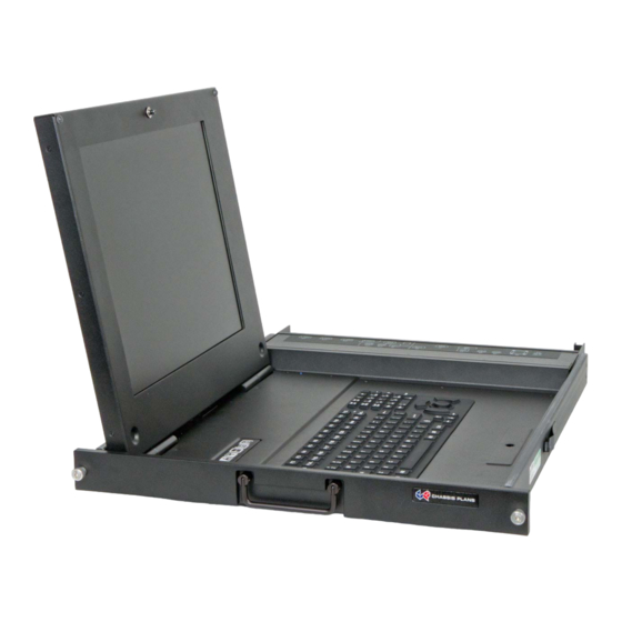
Chassis Plans CCIR-17 Technical Reference Chapter 1 - Introduction Photos Photo 1- Front View – Open Photo 2- Front View – Closed Photo 4- Side View Photo 3- Top View of Keyboard Area (w/ KVM) Photo 5- Rear View w/ 4-Port KVM... -
Page 12: Photo 6- Nema-4 / Ip65 Keyboard W/ Hula Point
Chassis Plans CCIR-17 Technical Reference Chapter 1 - Introduction Photo 6- NEMA-4 / IP65 Keyboard w/ Hula Point Photo 7- NEMA-4 / IP65 Keyboard w/ Touch Pad Page 10... -
Page 13: Specifications
Chassis Plans CCIR-17 Technical Reference Chapter 1 - Introduction Specifications Enclosure KEYBOARD 1U (1.71”) x 24.6” deep Sealed silicone rubber keyboard Front Panel milled 5052 aluminum alloy 97 keys w/ 12 function keys and touch pad Body made of 5052-H32 aluminum alloy... -
Page 14: Lcd Dvi/Vga Input Features
Chassis Plans CCIR-17 Technical Reference Chapter 1 - Introduction LCD DVI/VGA Input Features: Inputs: Analog RGB: 60Hz at SXGA, WXGA, XGA, SVGA, VGA With auto detect of Digital Separate Sync, Sync-On-Green & Composite Sync. Auto detects VGA ~SXGA interlaced &... - Page 15 Chassis Plans CCIR-17 Technical Reference Chapter 1 - Introduction Figure 1 – CCIR-17 Customer Drawing Page 13...
-
Page 16: Lcd Enhancements
LCD, but to also enhance the mechanical, optical and EMI properties of the finished unit Chassis Plans optically bonds 2 layers of coated 1.1 mm soda-lime float glass to the front of the LCD panel. The first layer is coated with an Indium Tin Oxide (ITO) coating with a surface resistivity of <13.5 ohms/sq. See Figure 2 for attenuation values. - Page 17 Chassis Plans CCIR-17 Technical Reference Chapter 1 - Introduction Without Optical Bonding With Optical Bonding Or AR Coating And AR Coating Reflected Reflected Light Light 0.3% 4.5% Total Total 0.1% 0.7% 22.5% 4.5% 4.5% 0.1% 0.1% 4.5% 4.5% 0.1% Figure 4 – Comparison of Reflections with and without Optical Bonding The resulting structure has greatly enhanced optical characteristics in high ambient light conditions.
- Page 18 Chassis Plans CCIR-17 Technical Reference Chapter 1 - Introduction This Page Intentionally Blank Page 16...
-
Page 19: Chapter 2 - Kvm Option
Chapter 2 – KVM Option KVM Option The CCIR-17 is designed to interface with an optional four-port VGA KVM module. This KVM allows the one keyboard/display to control four VGA ports with PS/2 or USB keyboard/mouse signals. The KVM provides OSD control using keyboard hotkey commands. -
Page 20: Kvm Connection
KVM Connection Cable Connections To set up your CCIR-17 with KVM, refer to the installation diagram on the following page (the numbers in the diagrams correspond to the steps below) and do the following: 1. Using the included short PS/2 and USB jumper cables, plug the outputs of the CCIR-17 Keyboard and Mouse (left side of rear panel) into the appropriate ports on the KVM side of the rear panel (right side). -
Page 21: Kvm Installation Diagram
Chassis Plans CCIR-17 Technical Reference Chapter 2 – KVM Option KVM Installation Diagram Figure 6 – Comparison of Reflections with and without Optical Bonding Page 19... - Page 22 Chassis Plans CCIR-17 Technical Reference Chapter 2 – KVM Option This Page Intentionally Blank Page 20...
-
Page 23: Chapter 3 - Power Supply Options
Chassis Plans CCIR-17 Technical Reference Chapter 3 – Power Supply Options Chapter 3 – Power Supply Options AC Input Power Supply The AC Input Power Supply is a 65W Medical Grade “Brick” style power supply. The output is provided with a circular mil connector for connecting to the LCD Keyboard Drawer. -
Page 24: 12Vdc Input Transient Filter
Chassis Plans CCIR-17 Technical Reference Chapter 3 – Power Supply Options 12VDC Input Transient Filter The CCI family display consoles require nominal +12VDC at 40W for operation. An EMI line filter is provided to limit EMI emissions and to provide a small measure of input filtering. -
Page 25: Mil-Std-704/1275 Dc Input Converter
Chassis Plans CCIR-17 Technical Reference Chapter 3 – Power Supply Options MIL-STD-704/1275 DC Input Converter The xx Mil-Std-704/1275 DC Input Converter provides true 704/1275 input specifications allowing reliable operation from nominal 28VDC input mains in a military environment. Amil grade DC to DC Converter is provided in a rack mountable case with military grade circular connectors. -
Page 26: Connectors
Chassis Plans CCIR-17 Technical Reference Chapter 3 – Power Supply Options +/-48VDC Power Supply The xx 48VDC Input Converter provides universal isolated 48VDC input, either positive or negative input. Thus it can be used in a data center with centralized power of +48VDC as well as a central office with -48VDC mains. -
Page 27: Chapter 4 - Ordering Information
Chassis Plans CCIR -17 Technical Reference Chapter 4 – Ordering Information Chapter 4 – Ordering Information CCIR = CP Clamshell Industrial Right Side Mount Base Unit Keyboard Options: A = NEMA 4/IP65 113-Key with pointing device (PS/2 or USB) B = NEMA 4/IP65 97-Key with touchpad (USB) Head Unit Options: 171A = 17”... - Page 28 Chassis Plans CCIR -17 Technical Reference Chapter 4 – Ordering Information This Page Intentionally Blank Page 26...
-
Page 29: Chapter 5 - Package Contents
For the DC input supplies, a kit is provided with a mating Mil Circular connector, backshell, and pins allowing the user to fabricate an appropriate cable for the intended application. For volume orders, Chassis Plans can provide pre-fabricated power cables per the end use specifications. Page 27... - Page 30 Chassis Plans CCIR -17 Technical Reference Chapter 5 – Package Contents This Page Intentionally Blank Page 28...
-
Page 31: Chapter 6 - Installation
Rack Installation To mount the CCIR-17 in a rack, it is first important you identify the correct holes to mount to. Please see the following illustration. Note that a ‘U’ starts between the holes that are ½” apart. One very common problem is trying to install into the wrong holes. -
Page 32: Connecting The Display
Photo 10 – LCD Controller Rear Panel I/O w/ KVM Table 8, following, details the connectors for the CCIR-17 with KVM installed. For installations without the KVM, disregard the second part of the table and connect the computer signals utilizing the included cables as indicated. - Page 33 Chassis Plans CCIR -17 Technical Reference Chapter 6 - Installation Legend Function Connector on KVM Notes Keyboard and LCD Signals 12VDC Power Input Power, 12VDC +/-5% Circular Mil N/S 3102A-10SL-3P Mouse PS/2 Output PS/2 - Locking Keyboard PS/2 Output PS/2 - Locking Keyboard/Mouse USB Output USB Type ‘A’...
- Page 34 Chassis Plans CCIR -17 Technical Reference Chapter 6 - Installation This Page Intentionally Blank Page 32...
-
Page 35: Chapter 7 - Lcd Operation
Chassis Plans CCIR -17 Technical Reference Chapter 7 – LCD Operation & OSDs Chapter 7 – LCD Operation Opening the LCD The LCD is equipped with a ¼-turn fastener to secure the LCD panel in the closed position for installation in environments with high levels of shock and/or vibration. -
Page 36: Lcd Front Panel Controls
Chassis Plans CCIR -17 Technical Reference Chapter 7 – LCD Operation & OSDs LCD Front Panel Controls The On Screen Display (OSD) is adjusted as follows: 1. Press the Menu Button located on the front of the monitor. 2. Use the buttons described below to maneuver around the Menu. -
Page 37: Osd Menus
Chassis Plans CCIR -17 Technical Reference Chapter 7 – LCD Operation & OSDs OSD Menus Select input source Input source 1 Select input source to Analog RGB Input source 2 Select input source to DVI Auto Source Seek ON – Auto source select always enable OFF –... - Page 38 Chassis Plans CCIR -17 Technical Reference Chapter 7 – LCD Operation & OSDs Position Autosetup* Auto adjust the positions, phase, frequency Frequency* Adjust the image horizontal size Phase* Fine tune the data sampling position (adjust image quality) Image Horizontal Use +/- to move the image horizontally Position* Press –...
-
Page 39: Chapter 8 - Kvm Programming
Powering Off and Restarting The KVM is self-powered in that it is powered by connections to the CCIR-17 and the connected computers. To turn the KVM off, it is necessary to remove all external power coming through the connected cables. If it becomes necessary to power off the KVM, before starting it back up, you must do the following. -
Page 40: Auto Scanning
3. To exit Auto Scan Mode, Press the [ESC] key or the [SPACEBAR]. Hotkey Setting Mode (HSM) Hotkey Setting Mode is used to set up the CCIR-17 KVM configuration. All operations begin with invoking the Hotkey Setting Mode (HSM). Invoking HSM To invoke HSM, do the following: 1. -
Page 41: Alternate Hsm Invocation Keys
Chassis Plans CCIR -17 Technical Reference Chapter 8 – KVM Programming Alternate HSM Invocation Keys An alternate set of HSM invocation keys is provided in case the default set conflicts with programs running on the computers. To switch to the alternate HSM invocation set, do the following: 1. -
Page 42: Keyboard Operating System Platform
Keyboard Operating System Platform The CCIR-17 KVM’s default port configuration is for PC compatible keyboard operating system. If your console uses a PC compatible keyboard and you have a MAC attached to a port, for example, you can change the port’s keyboard operating platform configuration so that the PC compatible keyboard emulates the MAC keyboard. -
Page 43: Disable Port Switching Keys
Chassis Plans CCIR -17 Technical Reference Chapter 8 – KVM Programming Disable Port Switching Keys To disable the Port Switching Keys ([SCROLL LOCK][SCROLL LOCK] or [CTRL][CRTL]) do the following: 1. Invoke HSM (see page 38). 2. Press [X][ENTER]. This is a toggle. To enable Port Switching, repeat steps 1 and 2. -
Page 44: Hsm Summary Table
Chassis Plans CCIR -17 Technical Reference Chapter 8 – KVM Programming HSM Summary Table After invoking HSM (see page 38), key in one of the following key combinations to perform the corresponding function. Function Key Operation Toggles between the default [NUM LOCK][-] and alternate [CTRL][F12] HSM invocation keys. -
Page 45: Keyboard Emulation
Chassis Plans CCIR -17 Technical Reference Chapter 8 – KVM Programming Keyboard Emulation MAC Keyboard The PC compatible keyboard can emulate the functions of the MAC keyboard. The emulation mappings are listed below: Table 17- MAC Keyboard Emulation Note: 1. When using key combinations, press and release the first key [CTRL], then press and release the activation key. -
Page 46: Sun Keyboard
Chassis Plans CCIR -17 Technical Reference Chapter 8 – KVM Programming Sun Keyboard The PC compatible keyboard can emulate the functions of the Sun keyboard when the Control key [CTRL] is used in conjunction with other keys. The corresponding functions are shown in the table below. -
Page 47: Hotkey Default Settings
Chassis Plans CCIR -17 Technical Reference Chapter 8 – KVM Programming Hotkey Default Settings Setting Hotkey Default Port Switching [SCROLL LOCK][SCROLL LOCK] Invoking HSM [NUM LOCK][-] Auto Scan Interval [SCROLL LOCK][SCROLL 5 Seconds LOCK][A][ENTER] PC Compatible Keyboard Operating Platform [F10]... - Page 48 Chassis Plans CCIR -17 Technical Reference Chapter 8 – KVM Programming This Page Intentionally Blank Page 46...
-
Page 49: Chapter 9 - Kvm Firmware Upgrade Utility
A firmware upgrade is generally not required unless you are having operation issues. Please check with the Chassis Plans Customer Service Department for instructions prior to uploading new Firmware into your CCIR-17 KVM. There are potential failure issues that require the unit be returned to Chassis Plans for repair if the Firmware upgrade is not successful. -
Page 50: Screen Shot 2 - Firmware Upgrade Utility Main Screen
Chassis Plans CCIR -17 Technical Reference Chapter 9 – KVM Firmware Upgrade Screen Shot 2 – Firmware Upgrade Utility Main Screen 4. As you select a device in the list, its description appears in the Device Description panel. After you have made your device selection, click [NEXT] to perform the upgrade. -
Page 51: Upgrade Successful
After a successful firmware upgrade completion, the KVM exits Firmware Upgrade Mode and resets itself. Upgrade Failed If the Upgrade Successful screen doesn’t appear, it means that the upgrade failed to complete successfully, in which case you should contact Chassis Plans Customer Service for a resolution. Page 49... - Page 52 Chassis Plans CCIR -17 Technical Reference Chapter 9 – KVM Firmware Upgrade This Page Intentionally Blank Page 50...
-
Page 53: Appendix A - Display Serial Control Programming
The OSD functions are controlled through the following RS-232 commands. The RS-232 program can be custom-tailored to fit the application or it can be used as provided by Chassis Plans on request. Please contact Chassis Plans for additional information. Function... - Page 54 Chassis Plans CCIR -17 Technical Reference Appendix A – Display Serial Control Programming Function Command Description Acknowledge (if enabled) Brightness 0x81, Set brightness = Brightness. control nn | “+” | “-” | value/increment/decrement “r” | “R” | Reset Range: “0””0”-“F””F”...
- Page 55 Chassis Plans CCIR -17 Technical Reference Appendix A – Display Serial Control Programming e.g “1””0” 0xe0 0x31 0x30 * This control can only function when JP2 sets 3-4 closed * Apply for inverter control voltage in range of 0~5V.
- Page 56 Chassis Plans CCIR -17 Technical Reference Appendix A – Display Serial Control Programming ASCII ASCII ASCII ASCII 0x30 0x41 0x61 0x2B 0x31 0x42 0x62 0x2D 0x32 0x43 0x63 0x3F 0x33 0x44 0x64 0x34 0x45 0x65 0x35 0x46 0x66 0x36 0x47...
-
Page 57: Appendix B - Auto Color Gain
Chassis Plans CCIR -17 Technical Reference Appendix B – Auto Color Gain Appendix B – Auto Color Gain The Auto Color Gain function is supported in the ARGB mode only and is designed to calibrate the controller to the incoming video signal. In order to calibrate correctly, the display must be displaying an image containing both black and white data (see illustration below) when the function is used. - Page 58 Chassis Plans CCIR -17 Technical Reference Appendix B – Auto Color Gain This Page Intentionally Blank Page 56...
-
Page 59: Appendix C - Troubleshooting The Kvm
Chassis Plans CCIR -17 Technical Reference Appendix C – KVM Troubleshooting Appendix C - Troubleshooting the KVM Operation problems can be due to a variety of causes. The first step in solving them is to make sure that all cables are securely attached and seated completely in their sockets. In addition, updating the product’s firmware may solve problems that have been discovered and resolved since the prior version was released. - Page 60 Chassis Plans CCIR -17 Technical Reference Appendix C – KVM Troubleshooting This Page Intentionally Blank Page 58...
-
Page 61: Appendix D - Dvi-D Versus Dvi-I Connectors
Chassis Plans CCIR-17 Technical Reference Appendix D – DVI-D versus DVI-I Appendix D – DVI-D versus DVI-I Connectors The Digital Visual Interface (DVI) is a video interface standard designed to provide very high visual quality on digital display devices such as flat panel LCD computer displays and digital projectors. It was developed by an industry consortium, the Digital Display Working Group (DDWG). - Page 62 Chassis Plans CCIR-17 Technical Reference Appendix D – DVI-D versus DVI-I This Page Intentionally Blank Page 60...
Need help?
Do you have a question about the CCIR-17 and is the answer not in the manual?
Questions and answers