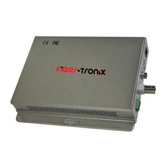
Summary of Contents for Fiber Tronix FT-FOTR-1VD-ST-S
- Page 1 INSTALLATION MANUAL FT-FOTR-1VD-ST-S 1-Channel Digital Duplex Baseband Video Transmitter and Receiver With Reverse Data Transmission for PTZ Cameras v1.0 4/5/11...
-
Page 2: Package Contents
PACKAGE CONTENTS This package contains: One each FT-FOTR-1VD-ST-S 1-channel baseband video transmitter and receiver Two 5VDC power supplies One installation manual PRODUCT DESCRIPTION The FT- FOTR-1VD-ST-S fiber optic transmitter/receiver supports the transmission of a single baseband video channel and a reverse data signal over one strand of single-mode fiber optic cable. -
Page 3: Unpacking And Handling
INSTALLATION AND OPERATION This symbol is intended to alert the user to the presence of important operating and maintenance (servicing) instructions. This symbol is intended to alert the user to the presence of “dangerous voltage” within the product’s enclosure that may be of sufficient magnitude to constitute a risk of electrical shock. -
Page 4: Special Attention
Receiver Front Panel Data port Video Power Input Optical port (Terminal block) Output (DC5V) (ST/PC) Video A B G Optical Power Link Power Data I/O Data Video RS485 A: Data Output + A B G B: Data Output – G: Ground Connection Data a. -
Page 5: Troubleshooting
5. TROUBLESHOOTING a. No picture after applying power – (i) check all connectors and cables are securely connected to the video source, monitor, transmitter and receiver; (ii) ensure all power supplies are providing the correct voltage and current. b. No image or poor image quality – determine if the optical signal loss is greater than 18 c.


Need help?
Do you have a question about the FT-FOTR-1VD-ST-S and is the answer not in the manual?
Questions and answers