Table of Contents
Advertisement
Quick Links
Advertisement
Table of Contents

Summary of Contents for Sirus ELXA400
- Page 1 User manual...
-
Page 2: Table Of Contents
Table of content Safety instructions ........................... 3 1.1. FOR SAFE AND EFFICIENT OPERATION ................3 Front View ............................4 2.1. Rear & Side Views ........................4 Introduction ............................5 3.1. Unpacking ..........................5 3.2. Installation and Mounting ......................5 Front Panel ............................6 4.1. -
Page 3: Safety Instructions
1. Safety instructions This device is suitable for indoor use only. All modifications to the device will void the warranty. Repairs are to carry out by skilled personnel only. Use only fuses of the same type and original parts as spare parts. Protect the unit from rain and humidity to avoid fire and electric shocks. -
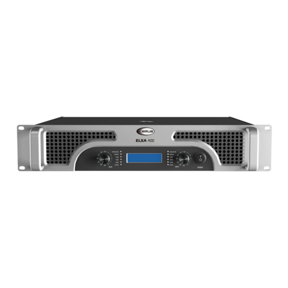
Page 4: Front View
Important: Damages caused by the disregard of this user manual are not subject to warranty. The dealer will not accept liability for any resulting defects or problems. Make sure the electrical connection is carried out by qualified personnel. All electrical and mechanical connections have to be carried out according to the European safety standards. -
Page 5: Introduction
3.2. Installation and Mounting ELXA Series amplifiers ELXA400 are 2-rack-space high. All mount in standard 19“ racks. Four front- panel mounting holes are provided on each amplifier. Rear mounting ears give additional support, and use of rear supports is highly recommended in all mobile and touring sound systems. -
Page 6: Front Panel
4. Front Panel 1. Rack Mounting Ears Two front panel mounting holes are provided on each mounting ear. 2. Fan Outlet Grills ELXA Series amplifiers are cooled by two rear-mounted fans. Cool air flows over the heat sinks and exhausts through the back grills. Make sure these outlets remain clean to allow unrestricted air flow. -
Page 7: Rear Side
4.1. Rear Side 10. Output Connectors These have two functions, on is binding post, the other is speakon. Connection to the binding post can be made with bare wire, banana plugs, or spade lug terminations. Make connections to both the channel A and channel B terminals for Stereo or Parallel Mode. Using speakon- type speaker cables, make connections to both the channel A and channel B connectors for Stereo of Parallel mode. -
Page 8: Operation
5. Operation 5.1. Connecting Power ELXA Series amplifier power requirements are rated at: a) „idle“ b) 1/8th power („typical“ music conditions) c) 1/3rd power („continuous“ music conditions) d) Maximum rated power (circuit breaker limited) The maximum power current draw rating is limited only by the front panel circuit breaker. Consult the specification in the Appendices section for figures on the current that each amplifier will demand. -
Page 9: Connecting Outputs
amplifiers are configured with “Pin 3 hot”). The unused connector can be used to jumper the audio input to another amplifier input. 5.4. Connecting Outputs Speakers are connected using 5-way Output Binding Post or Speakon connector, depending on version supplied. Please note that on the 5-way Output Binding Post version of the ELXA, two pairs of 5-way binding posts are provided for each channel, so that paralleling of speakers is possible. -
Page 10: Stereo Mode Connections
Connecting amplifier outputs to oscilloscopes or other test equipment while the amplifier is in bridged mode may damage both the amplifier and test equipment!!! 6.4. Stereo Mode Connections 6.5. Parallel Mode Connections 10 / 17... -
Page 11: Bridged Mono Mode Connections
6.6. Bridged Mono Mode Connections 7. LX Clip Limitting At the amplifier’s full power limit, or clipping point, LX will be activated. This is indicated by an illumination of the Limiter LED. The channel gain is automatically reduced, protecting the loudspeakers from potential damage from the high power, continuous square waves that would otherwise be produced. -
Page 12: Lrs Short Circuit Protection
LRS Short Circuit Protection If an output is shorted (i.e. defective speakers or crossed speaker wires) the LRS will automatically protect the amplifier. The load will be disconnected by the thermal protection circuitry (output relay opens) and the amplifier will be shut down. Please remove the short circuit and switch on the amplifier again to restart the amplifier. -
Page 13: Appendices
Appendices Amplifier specifications 13 / 17... - Page 14 14 / 17...
- Page 15 15 / 17...
- Page 16 16 / 17...
- Page 17 Importeur: B & K Braun GmbH Industriestraße 1 D-76307 Karlsbad www.bkbraun.com info@bkbraun.com 17 / 17...
Need help?
Do you have a question about the ELXA400 and is the answer not in the manual?
Questions and answers