Table of Contents
Advertisement
Advertisement
Table of Contents

Summary of Contents for Acom 1011
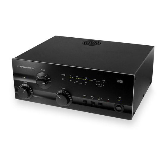
- Page 1 HF LINEAR AMPLIFIER...
-
Page 2: Table Of Contents
Table of Contents 1. GENERAL INFORMATION ........3 1-1. - Page 3 We express our thanks to Jim Talens, N3JT for his editorship and Ron Stone, GW3YDX for his comments and suggestions...
-
Page 4: General Information
If technical or operating assistance is needed, your local dealer should be contacted first. In the unlikely event you need further information, you may get in touch with ACOM by facsimile, telephone, email or standard mail. Fax: + 359 2 920 9656; telephone: + 359 2 920 9655; e-mail: acom@mail.orbitel.bg;... -
Page 5: Safety Considerations, Explicit Definitions
Antenna selection. Two antenna outputs are selectable on the front panel of the amplifier. Efficient tuning. Antenna matching can be achieved in less than 10 seconds and at a quarter of nominal output power, which produces lower risk of interference to other stations and greater safety to the amplifier components. -
Page 6: Installation
CAUTION To avoid damage to the amplifier not covered by ACOM’s warranty, the user is expected to read and comply with the installation instructions contained in Section 2 of this operating manual. If there are any doubts or questions concerning installation, operation or safety of the amplifier, the user should contact ACOM. -
Page 7: Line Voltage Selection
Left tube s/n Right tube s/n Voltage Selector Table 2-1. ACOM 1011 Individual Data 2-3. Amplifier Location Selection Locate the amplifier as close as possible to where it can be used conveniently. Access to the command knobs and indicator’s area, as well as to the rear panel cabling, will be necessary. - Page 8 FUSE 5x20 FUSES DANGER! HIGH VOLTAGE INSIDE ! 100-120V: 10A MODEL: ACOM 1011 200-240V 6.3A FOLLOW INSTRUCTIONS PRECISELY DISCONNECT AC POWER SERIAL NO.: BEFORE REMOVING COVER ! 100-120 or 200-240 V 50-60 Hz 1200 VA FCC ID: RF INPUT ANT 1...
-
Page 9: Power On, Controls And Indicators
WARNING If your amplifier is only fitted with one line (mains) fuse, it is suitable for the European Community ONLY. Your dealer will check that your amplifier is correctly fused before it is shipped to you, based upon your indicated location. Customers should check with a qualified electrician if the amplifier is to be used outside the country in which it was purchased. - Page 10 BAND G1 G2 IP 18-21 24-28 LOAD TUNE OPER RTTY Fig. 3-1 ACOM1011 Display and Control Note that the upper LED bar-graph always reads peak forward power, except for the service functions (Section 5-5). The 800 W-scale resolution is 50 W. Note also that levels below 50 W may be not detected.
-
Page 11: Operation
4. OPERATION Operation of the amplifier is simplified through ACOM’s innovative TRI tuning aid, Auto-Operate function, and automatic protection systems. To make full use of the amplifier’s potential and to configure it to local conditions, the following information should be read carefully. -
Page 12: Rtty Mode
4-3. RTTY Mode Select the RTTY mode to operate continuous-duty modes such as RTTY, SSTV, or other data modes. The LED indicator above the RTTY button illuminates and the amplifier operating parameters are changed to reduce tubes dissipation. In the RTTY mode, the amplifier output power is reduced to a maximum of 500 W. - Page 13 CAUTION At elevated VSWR levels, high voltages and high currents are distributed along the coaxial cable to the antenna, risking internal arcing and heat generation, and likely damage to the cable and any antenna switches that may be used. It is recommended that VSWR levels of more than 3:1 not be permitted with coaxial cable above 14 MHz.
-
Page 14: The Auto-Protection System
(3) Watch the TRI indicator above the LOAD (left hand) capacitor and turn the LOAD capacitor in the indicated direction to center the green LED indicator light. (4) Increase the drive power to get the desired nominal output; then repeat steps (2) and (3), always peaking output with the TUNE adjustment. -
Page 15: Maintenance
- if one of the yellow (G1, G2, IP) warning LEDs is illuminated along with the “F” LED, a current limit has been exceeded; drive power must be reduced or retuning is necessary; - if the last red LED of the reflected-power bar-graph is illuminated together with the “F” LED, the reflected-power limit has been exceeded;... -
Page 16: Tubes Replacement
MAINS PCB: 0.8 A 250 V SLOW BLOW (Time Lag) 5 x 20 mm; BUSSMANN type S504-800mA These latter fuses must not be replaced by the user. Replacing these internal fuses is potentially dangerous and must be done only by a trained service technician. Contact your ACOM dealer for assistance. 5-3. Tubes Replacement Two 4CX250B (7203) ceramic-metal tetrodes are used in the amplifier. -
Page 17: Service Functions
Many software-derived protections are based on this information. * Detailed electrical schematic diagrams are available from ACOM or from your dealer on request. 5-5. Service Functions By pressing the OPER and RTTY buttons simultaneously, the upper LED bar-graph is switched to the service mode, which is indicated by both red bar-graph lights and the yellow G1 light illuminating. -
Page 18: Functions
- Bypass path: VSWR less than 1.1:1, 1.8-30 MHz continuously, 200 W maximum; - Output (antenna) impedance matching capability: VSWR up to 3:1 or higher. g) RF Gain: 11dB typically, frequency response less than 1dB (50 to 70 W drive power for rated output). -
Page 19: Storage And Shipment
6-3. Storage and Shipment CAUTION Should it be necessary to ship the amplifier, use the original packing as described below. Switch off the amplifier, pull the line (mains) plug out of the outlet, disconnect all cables from the rear panel of the amplifier (remove the ground connection the last), and then pack the amplifier in its original carton.
Need help?
Do you have a question about the 1011 and is the answer not in the manual?
Questions and answers