Table of Contents
Advertisement
Quick Links
Installation and operating instructions
for the MAX CADDY wood furnace
CERTIFIED ACCORDING TO CSA B415.1-10, CAN/CSA B366.1 M91,UL391 4
NO.236-05, UL 1995 3
FURNACE MODELS INCLUDED IN THIS MANUAL
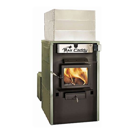
MAX CADDY WOOD AND COMBINATION FURNACE
Read these instructions carefully before installing
You have purchased one of the finest wood or combination furnaces
available on the market. We are confident that your furnace will provide
years of comfort and safe operation.
This manual is available for free download on the manufacturer's web site. It is a
copyrighted document. Re‐sale is strictly prohibited. The manufacturer may update this
manual from time to time and cannot be responsible for problems, injuries, or damages
arising out of the use of information contained in any manual obtained from
unauthorized sources.
Printed in Canada
(PF01101 model)
READ THE MANUAL THOROUGHLY
BEFORE OPERATING THE FURNACE
RD
EDITION 2003, CSA B140.4-04 AND UL 727 9
20kW/25kW and UH-Max Caddy
and operating your furnace.
CONGRATULATIONS!
PSG
250 de Copenhague
Saint-Augustin-de-Desmaures
Quebec, Canada
G3A 2H3
TH
EDITION 2006, CAN/CSA C22.2
TH
EDITION 2006
Please keep this document!
45446A
05-05-2015
Advertisement
Table of Contents

Summary of Contents for PSG MAX CADDY PF01101
- Page 1 250 de Copenhague Saint-Augustin-de-Desmaures Quebec, Canada G3A 2H3 Installation and operating instructions for the MAX CADDY wood furnace (PF01101 model) READ THE MANUAL THOROUGHLY BEFORE OPERATING THE FURNACE CERTIFIED ACCORDING TO CSA B415.1-10, CAN/CSA B366.1 M91,UL391 4 EDITION 2006, CAN/CSA C22.2 NO.236-05, UL 1995 3 EDITION 2003, CSA B140.4-04 AND UL 727 9 EDITION 2006...
-
Page 2: Table Of Contents
TABLE OF CONTENT WOOD OR WOOD/ELECTRIC COMBINATION FURNACES ............5 1. CHIMNEY AND DRAFT ........................5 2. SAFETY RULES ............................. 5 GENERAL REQUIREMENTS ...................... 5 ODOUR FROM THE PAINT ......................6 ASH DISPOSAL ..........................6 ... - Page 3 MODES, OPTIONS AND PROGRAMMING ................30 4.5.1 The speeds ..........................30 4.5.2 System Balancing ........................31 4.5.3 HEAT Mode (automatic heating) ....................31 4.5.4 COOL Mode (air conditioning) ....................31 4.5.5 ...
- Page 4 IMPORTANT NOTE: THE INSTALLATION OF THIS CENTRAL HEATING SYSTEM MUST BE PERFORMED BY A QUALIFIED TECHNICIAN. PSG RESERVES ITSELF THE RIGHT TO VOID ITS WARRANTY OR DENY TECHNICAL ADVICE IF THE FURNACE HAS NOT BEEN SOLD OR INSTALLED BY A PROFESSIONAL.
-
Page 5: Wood Or Wood/Electric Combination Furnaces
SECTION A: WOOD OR WOOD/ELECTRIC COMBINATION FURNACES Take note that this furnace operates like an EPA wood burning stove. This applies to the lighting, the ember bed, and the minimum combustion air intake which was determined based on the use of good seasoned cordwood. The Max Caddy furnace was tested and approved according to the CSA B415.1-10 Standard. -
Page 6: Odour From The Paint
WARNING THE ASH DRAWER AND EXCHANGERS ACCESS PANEL GET VERY HOT. DO NOT MANIPULATE WITH BARE HANDS. ODOUR FROM THE PAINT It is normal that smoke and odours emanate from the unit when you first light it. It is recommended to burn it at high rate and ventilate the building until the odours disappear. -
Page 7: Glass Specifications
The glass is made of 3/16” (5mm) thick Pyroceram. Do not operate your wood furnace with a broken glass, as this could seriously damage your furnace. You can purchase a replacement glass from your PSG dealer. ASH DRAWER Your furnace is equipped with an ash drawer to collect ashes produced by the combustion of wood. This drawer must not be left open during combustion as this may cause over firing and serious damages to the furnace. -
Page 8: Appliance Installation
3. APPLIANCE INSTALLATION The installation instructions of this section apply to the wood-only Max Caddy, the wood-electric Max Caddy, the wood-oil Max caddy, and the wood-oil-electric trio Max Caddy. WARNING : THE INSTALLATION OF THIS APPLIANCE REQUIRES THE ADITION OF A BLOWER BOX &... -
Page 9: Cold Air Return Box Installation
COLD AIR RETURN BOX INSTALLATION Before installing the cold air return box, you need to remove the back panel gasket and the back panel as shown below. To do so, remove the 8 screws. - Page 10 Remove the cold air ducting support from the cold air return box. To do so, remove the 12 screws as shown below. Keep these screws. You will need them to install the cold air ducting support in the new location.
-
Page 11: Cold Air Ducting Support Installation
Then, secure the cold air return box to the furnace. To do so, use the 8 screws as shown below. Then, level the cold air return box by screwing or unscrewing the elevator bolts. COLD AIR DUCTING SUPPORT INSTALLATION On the cold air return box, you will find two side plates and the cold air return box door. The cold air ducting support can be configured in several ways. - Page 12 Installation of the cold air ducting support at the RIGHT of the cold air return box Installation of the cold air ducting support at the LEFT of the cold air return box...
- Page 13 Installation of the cold air ducting support ON TOP of the cold air return box with filter exit towards the RIGHT Installation of the cold air ducting support ON TOP of the cold air return box with filter exit towards the LEFT...
-
Page 14: Control Pcb Installation And Connection
CONTROL PCB INSTALLATION AND CONNECTION The control PCB may be installed on either side of the furnace. Remove the 4 screws secured on the side of the furnace where you wish to install the control PCB, either on the left or on the right side, and keep these screws. Remove the access panel of the control PCB. - Page 15 Now, it is time to make the connection between the control PCB and the blower. Since the control PCB may be installed on either side of the furnace, refer to the drawings below to run the wire properly. Control PCB installed on the RIGHT side of the furnace Control PCB installed on the LEFT side of the furnace...
-
Page 16: Rtd Support Bracket Installation And Connection (Resistance Temperature Detector)
RTD SUPPORT BRACKET INSTALLATION AND CONNECTION (resistance temperature detector) Your Max Caddy furnace is equipped with a RTD probe (resistance temperature detector). This RTD probe must be installed on the RTD support bracket. The RTD support bracket may be installed on left side or on the right side of the furnace. - Page 17 Once the RTD probe is installed on the RTD support bracket, you need to connect the RTD probe to the control PCB. To run the wire properly, refer to the drawings below. Refer to the electric wiring diagram in section 7 for the electrical connections.
-
Page 18: Servomotor Installation And Connection
SERVOMOTOR INSTALLATION AND CONNECTION Your Max Caddy furnace is equipped with a servomotor. You need to secure it in place in the two pre-drilled holes using two screws as shown below. Once installed, you need to install the chain that links the air inlet damper to the servomotor as shown below. For more information regarding this installation, refer to the furnace owner’s manual. - Page 19 Then, you need to connect the servomotor to the control PCB. To do so, refer to the electric wiring diagram in section 7. To run the wire properly, refer to the drawings below. Wire running to the control PCB installed on the LEFT side of the furnace Wire running to the control PCB installed on the RIGHT side of the furnace WARNING: USE WIRING SUITABLE FOR 75 C (not supplied)
-
Page 20: Handles Installation
HANDLES INSTALLATION The following step consists of installing the handles on the handle rods of the ash drawer and the door as shown below. UNIT LOCATION The furnace must be installed where outside air supply is sufficient for proper combustion. In airtight houses, it might be necessary to install an outside air intake. -
Page 21: Clearances To Combustibles And Floor Protector
CLEARANCES TO COMBUSTIBLES AND FLOOR PROTECTOR N.B. This appliance must be installed according to the instructions on the unit’s certification label. HEAT SHIELD CEILING 72" HEAT SHIELD 3/4" 1" 3/4" 6" 18" HOT AIR PLENUM 8" MIN 24" 45° ELBOW STATIC PRESSURE CHECK POINT... - Page 22 CLEARANCES 24’’ (610 mm) recommended for maintenance 24’’ (610 mm) – Note 1 48’’ (1219 mm) Note 1: 24’’ (610 mm) recommended for maintenance on the option’s side (combo units). FLOOR PROTECTOR* CANADA 18’’ (457 mm) 16’’ (406 mm) From door opening From door opening N/A (USA only) 8’’...
-
Page 23: Flue And Barometric Draft Control Connection
FLUE AND BAROMETRIC DRAFT CONTROL CONNECTION Before connecting the stove pipe, make sure you have removed any accessory from the flue pipe such as the scraper, shovel, and the poker. The flue outlet on the Max Caddy furnace is 6” in diameter and the wood only or wood/electric models may be installed with a 6”... -
Page 24: Damper
amper 3.9.1 If the draft exceeds 0.06 INW.C., a barometric damper must installed. The barometric damper must be adjusted so that the maximum draft measured at the furnace outlet is limited to 0.06 IN.W.C. Please note that a draft higher than 0.06 IN.W.C. -
Page 25: Parallel Installation
NOTE: It is recommended to install an outside air inlet with a diameter of at least 4 inches in the room where the heating appliance is installed (see drawing below). It is preferable to choose a wall which is not exposed to dominant winds, depending on the conditions surrounding your house. -
Page 26: Electrical Element Installation - Wood-Electric Max Caddy (Optional)
3.12 ELECTRICAL ELEMENT INSTALLATION – WOOD-ELECTRIC MAX CADDY (OPTIONAL) The high limit control is a manual reset thermostatic sensor that is located inside the electrical unit. The electric unit must be connected as shown on the diagram (see WIRING DIAGRAM). The connections must conform to the diagram. -
Page 27: Thermostat Installation
PC Board, will be activated and deactivated at the same temperatures as the water solenoid valve (140°F et 120°F). Complete installation and operation instructions for the hot water loop kit are supplied with the kit and can be downloaded from the PSG web site at www.psg-distribution.com. -
Page 28: Installation Of An Air Conditioning Unit
3.15 INSTALLATION OF AN AIR CONDITIONING UNIT The MAX Caddy wood furnace has been tested with an optional air conditioning unit. If this option is chosen, we recommend an installation as per the graphic provided below. This installation will provide the most efficient and safe operation of the air conditioning unit using the distribution blower of the MAX Caddy furnace during summer. -
Page 29: Operating Instructions
4. OPERATING INSTRUCTIONS CONTROL SYSTEM On the Max Caddy furnace, a new electronic control was developed. This system is more polyvalent. All connections are done from the PC board. There are connector ports available for all components and options. Under the HEAT mode, a logic was developed to provide you with the best comfort and efficiency;... -
Page 30: The Use Of The "Bi-Energy" Function
4.3.1 The use of the “BI-ENERGY” function The bi-energy function is used when a local utility company (Hydro-Quebec for instance) offers a bi-energy program under which a preferential rate is given, provided that the appliance is equipped with an electronic control that guaranties the use of a particular source of energy (ex: electricity) based on a given criterion (ex: the outdoor temperature). -
Page 31: System Balancing
4.5.2 System Balancing It is important to call upon a professional installer for the installation of the furnace and the ducting system configuration. Certain check-ups must be performed and certain rules must be respected in order not to damage the blower. -
Page 32: Circ (Air Circulation)
4.5.5 CIRC (air circulation) Operation This mode is used to circulate air during summer. Thus you will benefit from your ducting system to circulate fresh air from your basement throughout the house. Programming In the MODE menu, select CIRC by pushing the SELECT button. Then, using the arrows buttons, choose from the different selections: TEMP, UNIT, or FAN. -
Page 33: Lighting
UNIT (measuring unit) By pushing the arrows, you will select the measuring unit that you wish to use (Fahrenheit or Celsius). Thereafter, temperatures will be displayed according to your selection. After two minutes of inactivity on the keyboard, the display will shut itself off. The UNIT selection has no impact on the operation of the furnace. It is simply a preference chosen by the technician or the user of the product.. -
Page 34: Early Signs Of An Overfired Furnace
EARLY SIGNS OF AN OVERFIRED FURNACE: 1. Roaring fire. 2. Chimney connector is glowing red. 3. Extreme heat coming from the furnace. If this occurs, DO NOT OPEN THE DOOR. Shut-off the air inlet opening completely, and wait until the glow has completely subsided. ALWAYS KEEP THE DOOR AND THE ASH DRAWER CLOSED (except for lighting and maintenance). -
Page 35: Maintenance
5. MAINTENANCE MAINTENANCE OF THE EXCHANGERS The flue pipe and the exchangers should be inspected regularly during the burning season. Easy access is provided (without the use of tools): simply unscrew the wing nut on the exchangers access door. See pictures below. WARNING: THE HEAT EXCHANGERS ARE TO BE CLEANED THOROUGHLY AT THE END OF EACH HEATING SEASON. -
Page 36: Chimney Maintenance
CHIMNEY MAINTENANCE The most efficient method to sweep the chimney is using a hard brush. Brush downwards so soot and creosote residues will come off the inner surface and fall at the bottom of the chimney where they can be removed easily. The chimney must be checked regularly and if creosote has accumulated, it must be removed without delay. -
Page 37: Replacement Parts
6. REPLACEMENT PARTS Your PSG furnace is designed to burn clean and requires little maintenance. It is recommended to conduct a visual inspection at least once a month to uncover any damage to the unit. Any defect must be repaired without delay using genuine PSG replacement parts. -
Page 38: General Electric Diagram With Beckett Oil Burner
7. GENERAL ELECTRIC DIAGRAM WITH BECKETT OIL BURNER... -
Page 39: General Electric Diagram With Riello Oil Burner
8. GENERAL ELECTRIC DIAGRAM WITH RIELLO OIL BURNER... -
Page 40: Electric Diagram With Optional Electrical Element
9. ELECTRIC DIAGRAM WITH OPTIONAL ELECTRICAL ELEMENT MAX CADDY WOOD/ELECTRIC COMBINATION FURNACE... -
Page 41: Max Caddy Technical Data
10. MAX CADDY TECHNICAL DATA "D" "E" "F" CADDY 57” 29 ¾” 48 ¾” 18 X 20” 32 ¼” "C" "G" 25 ½” 45” FLUE 6” or 7”* PIPE 650 lbs WEIGHT "A" "B" * Reducer required 10.1 GENERAL TECHNICAL DATA TEMP STATIC MODEL... -
Page 43: Trouble Shooting
12. TROUBLE SHOOTING PROBLEM CAUSES SOLUTIONS Heating inefficient during the first Improper adjustment of the Adjust the damper, minimize the combustions. Lack of draft. barometric damper (opened too chimney length and use 45 wide). Chimney flue restriction elbows. (too long, 90 elbows) Furnace heats well, warm air Improper installation of the ducts,... -
Page 44: Section B
SECTION B WOOD/OIL COMBINATION FURNACE INSTALLATION AND OPERATION INSTRUCTIONS FOR UH-MAX CADDY WOOD/OIL COMBINATION FURNACE READ THIS MANUAL THOROUGHLY BEFORE OPERATING THE FURNACE CAUTION CAUTION EXPLOSION OR FIRE HAZARD. FOR YOUR DO NOT ATTEMPT TO LIGHT THE SAFETY: DO NOT STORE OR USE BURNER WHEN EXCESS OIL HAS GASOLINE OR ANY FLAMMABLE LIQUIDS ACCUMULATED, WHEN THE APPLIANCE... -
Page 46: General Notes
GENERAL NOTES This instructions manual treats mainly of the oil burning unit of your wood/oil combination furnace. For any additional information concerning this wood burning furnace, please consult Section A of this manual. To obtain the maximum efficiency out of your furnace, follow the advice below regarding the installation and operation of your WOOD/OIL combination furnace. -
Page 47: Appliance Installation
The " barometric damper provided with the appliance must be installed on the oil unit evacuation pipe, approximately 24 from the flue outlet of the unit. TYPE OF FURNACE (UH) OIL BURNING UNIT FLUE PIPE DIAMETER PSG/ UH-MAX CADDY 5”... -
Page 48: Possible Installations
POSSIBLE INSTALLATIONS FOR THE WOOD/OIL MAX CADDY WALL ELBOW 45° MINIMUM DRAUGHT IN WOOD FLUE PIPE 0.04" W.C. Ø7" REDUCER 7" À 6" T CONNECTOR BAROMETRIC DAMPER 5" DRAFT 0.02" W.C. VERIFICATION HOLE FOR OIL COMBUSTION FURNACE TYPE CHIMNEY PIPE DIAMETER MAX CADDY *7"... -
Page 49: Combustion Air
COMBUSTION AIR Consult Section A of this manual for more details. ELECTRICAL WIRING The whole wiring from the distribution panel to the heating unit shall comply with the applicable electrical standards and local codes. The unit should be connected to its own 15 amp/120VAC electric circuit. Consult section A of this manual for the electrical wiring diagram using a Beckett or Riello burner. - Page 50 Before turning on the oil unit, make sure that the sealed vision cap (SE53352) is installed and secured on the vision tube with the screw provided. The chamber is calibrated so that there is a slight positive pressure, which optimizes the efficiency of combustion.
-
Page 51: Electrodes Setting
3.11 ELECTRODES SETTING The electrodes must be adjusted by a qualified technician. A proper positioning of the electrodes is important to get an efficient lighting of the oil. ELECTRODE SETTING FOR "F" HEAD 5/32" ELECTRODE 7/16" 1/16" NOZZLE WARNING: 1. REFER TO THE RATING PLATE FOR THE PUMP PRESSURE AND THE NOZZLE TYPE. 2. -
Page 52: 7- Electrical Diagrams
SERVICE Before calling for service, first check the following Fuel supply Electric fuses or breakers Thermostat setting PC board settings The state of the green diagnostic LED on the burner control. MAINTENANCE WARNING: Turn off electric power supply before servicing the unit. 1. -
Page 53: 8- Technical Data
8- TECHNICAL DATA UH – MAX CADDY BURNER STATIC PRESSURE H.P. FAN TUBULATOR MODEL NOZZLE FLOW HEAD EFFICIENCY TYPE INPUT PLATE AT THE PUMP MOTOR ADJUSTMENT ADJUSTMENT UH–MAX BECKETT 0.65, 70 0.65 GAL US/H 100 PSI 91,000 ½ CADDY (DELAVAN) (2.46 L-H) (690 kPa) UH–MAX... -
Page 54: Exploded Diagram And Parts List
EXPLODED DIAGRAM AND PARTS LIST... - Page 55 IMPORTANT : THIS IS DATED INFORMATION. When requesting service or replacement parts for your stove, please provide the model number and the serial number. We reserve the right to change parts due to technology upgrade or availability. Contact an authorized dealer to obtain any of these parts. Never use substitute materials. Use of non- approved parts can result in poor performance and safety hazards.
- Page 56 Item Description AC06900 BLACK 1/2'' ROUND X 9' GASKET KIT WITH ADHESIVE SE56322 PRIMARY AIR DAMPER ASSEMBLY 21341 AIR CONTROL PLATE GASKET PL56358 PRIMARY AIR DEFLECTOR 30060 THREAD-CUTTING SCREW 1/4-20 x 1/2" F HEX STEEL SLOT WASHER C102 ZINC PL56276 ASH SHELF SE51285 FURNACE 16'' ASH DRAWER...
- Page 57 Item Description SE56305 LEFT PANEL WITH INSULATION WATER LOOP OPTION PL36116 3 1/2" X 5 1/8'' X 1 1/4'' REFRACTORY BRICK 24099 CAST IRON ASH GRATE 12" X 7" PL36131 4" X 9'' X 3'' X 1/2'' REFRACTORY BRICK PL36059 CUT BRICK 4"...
-
Page 58: Why Purchase Through An Authorized Psg Dealer
Given the importance of the installation, PSG recommends that it is carried out by a professional certified in the Building Code so that the furnace delivers its full potential. This is why PSG offers an additional warranty that covers the cost of labor if your furnace has been purchased through an authorized PSG dealer. -
Page 59: Psg Limited Lifetime Warranty (Regular)
Firebrick *Pictures required Shall your unit or a components be defective, contact immediately your PSG dealer. Prior to your call make sure you have the following information necessary to your warranty claim treatment: Your name, address and telephone number;... -
Page 60: Psg Limited Lifetime Warranty (Privilege)
1 year and ceramic fibre blankets. Firebrick *Pictures required Shall your unit or a components be defective, contact immediately your PSG dealer. Prior to your call make sure you have the following information necessary to your warranty claim treatment: ...