Table of Contents
Advertisement
Quick Links
Advertisement
Table of Contents

Related Manuals for Kenwood CK 404


Summary of Contents for Kenwood CK 404
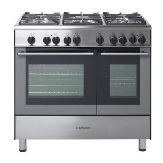
- Page 1 DUAL FUEL DOUBLE OVEN COOKER CK 404 Instructions for use - Installation advice...
- Page 2 Dear Customer, Thank you for purchasing a Kenwood Dual Fuel Double Oven Cooker The safety precautions and recommendations in these instructions are for your own safety and that of others. They will also provide a means by which to make full use of the features offered by your appliance.
-
Page 3: Table Of Contents
CONTENTS Page Number Introduction ........3 Important Safeguards &... -
Page 4: Important Safeguards & Recommendations
IMPORTANT SAFEGUARDS Fire risk! Do not store flammable material in the oven or in the storage AND RECOMMENDATIONS compartment. Make sure that electrical cords con- After unpacking the appliance, check to necting other appliances in the proxim- ensure that it is not damaged and that ity of the cooker cannot come into con- the oven door closes correctly. -
Page 5: Cooking Hob
1 - COOKING HOB Fig. 1.1 COOKING HOB 1. Auxiliary burner (A) 1,00 kW 2. Semi-rapid burner (SR) 1,75 kW 3. Rapid burner (R) 3,00 kW 4. Triple-ring burner (TR) 3,50 kW Note: The electric ignition is incorporated in the knobs. -
Page 6: Control Panel
2 - CONTROL PANEL Fig. 2.1 CONTROL PANEL - Controls description 1. Front right burner control knob 2. Rear right burner control knob 3. Central burner control knob 4. Rear left burner control knob 5. Front left burner control knob 6. -
Page 7: Use Of Cooking Hob
3 - USE OF COOKING HOB GAS BURNERS The maximum setting permits rapid boil- ing of liquids, whereas the minimum set- Each burner is controlled by a gas tap ting allows slower warming of food or which opens and closes the gas supply. maintaining simmering conditions of liq- Line the control knob symbol up with the uids. - Page 8 DEEP FAT FRYING CHOICE OF THE BURNER For safety purposes when deep fat fry- On the control panel, near each knob, ing, do not fill the pan more than one there is a diagram that indicates which third full of oil. burner is controlled by that knob.
-
Page 9: Fan Main Oven
4 - FAN MAIN OVEN WARNING: Attention: the oven door becomes The door is hot, use the handle. very hot during operation. During use the appliance becomes Keep children away. hot. Care should be taken to avoid touching heating elements inside the oven. - Page 10 TEMPERATURE KNOB (fig. 4.1) HOT AIR COOKING To turn on the heating elements of the oven, set the switch knob on the desired The circular element and the fan are on. program and select the required temper- The heat is diffused by forced convec- ature.
- Page 11 COOKING ADVICE SIMULTANEOUS COOKING OF DIFFERENT FOODS STERILIZATION The FAN consents a simultaneous het- Sterilization of foods to be conserved, in erogeneous cooking of different foods. full and hermetically sealed jars, is done Different foods such as fish, cake and meat can be cooked together without in the following way: mixing the smells and flavours together.
-
Page 12: Conventional Oven
5 - CONVENTIONAL OVEN OPERATING PRINCIPLES Attention: the oven door becomes Heating and cooking in the CONVEN- very hot during operation. TIONAL oven are obtained in the follow- Keep children away. ing ways: a. by natural convection GENERAL FEATURES The heat is produced by the upper and lower heating elements. - Page 13 OVEN COOKING OVEN LIGHT Before introducing the food, preheat the oven to the desired temperature. By setting the knob to this position, only For a correct preheating operation, it is the oven light comes on (15 W). advisable to remove the tray from the It remains on in all the cooking modes.
-
Page 14: Cooking Guide
6 - COOKING GUIDE Temperature and times given are approximate, as they will vary depending on the quality and amount of food being cooked. Remember to use ovenproof dishes and to adjust the oven temperature during cooking if necessary. COOKING CHART Temperature Food Cooking Time (approx) -
Page 15: 120 Minutes Timer
7 - 120 MINUTES TIMER 120 MINUTES TIMER Fig. 7.1) The timer can be set to a maximum of 120 minutes and a buzzer will sound at the end of the countdown. The knob must be rotated clockwise as far as the 120 minutes position first and then set to the required time by rotating it anticlockwise. -
Page 16: Cleaning & Maintenance
8 - CLEANING AND MAINTENANCE STAINLESS STEEL SURFACES Important: Can be cleaned with an appropriate Before cleaning or carrying out stainless steel cleaner. any maintenance disconnect the appliance from the electrical sup- ply and wait for it to cool down. WARNING Attention When correctly installed, your product... - Page 17 GAS TAPS CORRECT REPLACEMENT OF THE BURNERS In the event of operating faults in the gas taps, call the After Sales Service It is very important to check that the Department. burner flame distributor F and the cap C has been correctly positioned (see figs. 8.1 - 8.2) - failure to do so can cause a BURNERS poor burner flame and/or damage to the...
- Page 18 TRIPLE RING BURNER The triple ring burner must be correctly positioned (see fig. 8.3); the burner rib must be enter in their logement as shown by the arrow. The burners must be correctly positioned so that they cannot rotate (fig. 8.4). Then position the cap A and the ring B (fig.
- Page 19 Fig. 8.6 OVEN DOOR STORAGE COMPARTMENT The storage compartment is accessible The internal glass panel can be easily through the pivoting panel (fig. 8.7). removed for cleaning by unscrewing the 2 retaining screws (Fig. 8.6) Do not store flammable material in the oven or in the storage com- partment.
- Page 20 INSIDE OF OVEN The oven should always be cleaned after use when it has cooled down. The cavity should be cleaned using a mild detergent solution and warm water. Suitable proprietary chemical cleaners may be used after first consulting with the manufacturers recommendations and testing a small sample of the oven cavity.
- Page 21 REMOVING THE OVEN DOOR Fig. 8.10A The oven door can easily be removed as follows: – Open the door to the full extent (fig. 8.10A). – Attach the retaining rings to the hooks on the left and right hinges (fig. 8.10B). –...
-
Page 22: Advice For The Installer
Advice for the installer IMPORTANT – The appliance is designed and approved for domestic use only and should not be installed in a commercial, semi commercial or communal environment. Your product will not be guaranteed if installed in any of the above environments and could affect any third party or public liability insurances you may have. -
Page 23: Installation
9 - INSTALLATION This cooker has class “2/1” overheating protection so that it can be installed next to a cabinet. If the cooker is installed adjacent to furniture which is higher than the gas hob cooktop, a gap of at least 50 mm must be left between the side of the cooker and the furniture. The furniture walls adjacent to the cooker must be made of material resistant to heat. - Page 24 FITTING THE ADJUSTABLE FEET The adjustable feet must be fitted to the base of the cooker before use. Rest the rear of the cooker on a piece of the polystyrene packag- ing exposing the base for the fit- ting of the feet. Fit the 4 legs by screwing them tight into the support base as Fig.
- Page 25 MOVING THE COOKER WARNING When raising cooker to upright posi- tion always ensure two people carry out this manoeuvre to prevent dam- age to the adjustable feet (fig. 9.5). WARNING Be careful: do not lift the cooker by the door handle when raising to the upright position (fig.
- Page 26 VENTILATION REQUIREMENTS The appliance should be installed into a room or space with an air supply in accordance with BS 5440-2:2000. For rooms with a volume of less than 5 m - permanent ventilation of 100 cm free area will be required. For rooms with a volume of between 5 m and 10 m a permanent ventilation of 50 cm...
-
Page 27: Gas Section
10 - GAS SECTION GAS INSTALLATION GAS CONNECTION IMPORTANT NOTE The installation of the cooker to Natural This appliance is supplied for use on Gas or LP Gas must be carried out by a NATURAL GAS only and cannot be used qualified gas engineer. - Page 28 GAS CONNECTION The gas supply must use the nearest gas inlet pipe which is located at the left or the right hand side at the rear of the appliance (fig. 10.1). The unused end inlet pipe must be closed with the plug interposing the gasket. Flexible hoses can be used where the sited ambient temperature of the hose does not exceed 70°C.
- Page 29 To avoid damage to the appliance gas rail inlet pipe the fittings should be tightened using two suitable spanners (fig. 10.2). After connection to the mains gas supply the couplings should be checked for gas soundness/tightness as per current regulations for the gas type being used Fig.
- Page 30 CONVERSION TO LPG 1 - Injectors replacement of top burners If the injectors are not supplied they can be obtained from the “Service Centre”. The diameter is marked on the injector in cents of millimetre. Select the injectors to be replaced according to the “Table for the choice of Fig.
- Page 31 TABLE FOR THE CHOICE OF THE INJECTORS Cat: 2H3+ G 30 - 28-30 mbar G 20 Nominal Reduced BURNERS G 31 - 37 mbar 20 mbar Power Power By-pass Ø injector By-pass Ø injector [kW] [kW] [1/100 mm] [1/100 mm] [1/100 mm] [1/100 mm] 1,00...
-
Page 32: Electrical Section
11 - ELECTRICAL SECTION N.B. For connection to the mains, do not use adapters, reducers or IMPORTANT: The cooker must be branching devices as they can cause installed in accordance with the overheating and burning. manufacturer’s instructions. Incorrect installation, for which the If the installation requires alterations to manufacturer accepts no responsi- the domestic electrical system, call an... - Page 33 TECHNICAL DATA ELECTRICAL FEEDER CABLE CONNECTION 230 V AC - 50 Hz To connect the supply cable: Fan Main oven - Remove the screws securing the – Grill element 2.00 kW cover “A” on the rear of the cooker – Circular element 2.50 kW (fig.
-
Page 34: Guarantee
GUARANTEE UK only If your appliance goes wrong within one year from the date you bought it, we will repair it (or replace it if necessary) free of charge provided: • you have not misused, neglected, or damaged it; • it has not been modified; •... -
Page 35: After Sales Service
AFTER SALES SERVICE If you require After Sales Service contact the MASTERCARE Domestic Appliance Helpline Telephone 08701 565550. Ser. Nr. Descriptions and illustrations in this booklet are given as simply indicative. The manufacturer reserves the right, considering the characteristics of the models described here, at any time and without notice, to make eventual necessary modifications for their construction or for commercial needs. - Page 36 code 1102951 ß3...
Need help?
Do you have a question about the CK 404 and is the answer not in the manual?
Questions and answers