
Summary of Contents for JFY tech SUNTWINS 3300TL
- Page 1 www.JFY-tech.com Solar Inverters INSTALLATION AND OPERATOR'S MANUAL Model number: SUNTWINS xxxxTL series for Australia Rev. 1.0...
- Page 2 www.JFY-tech.com REVISION TABLE Document Author Date Change Description Revision Falcon.Tang 10/08/2011 First release SAVE THESE INSTRUCTIONS ! IMPORTANT SAFETY INSTRUCTIONS JFY-tech: Reproduction and disclosure of the contents of this manual are strictly forbidden without prior authorization of JFY-tech.
- Page 3 www.JFY-tech.com General notes The SUNTWINS is a transformerless solar inverter with two channels input of MPPT,and it converts the DC current of PV generator to AC current and feed it into the public grid.When you chose it,you have opted for reliable and powerful technology.With protection class IP65,the units are ready for use in all environmental conditions,and high efficiency meets your requirements.
- Page 4 www.JFY-tech.com Keep the whole surface of the photovoltaic panel covered with material opaque to solar radiation before connecting panel to equipment; this will ensure that no dangerous high voltage is present at the connection cables. This unit is designed to feed power to the public power grid (utility) only. Do not connect this unit to an AC source or generator.
-
Page 5: Table Of Contents
www.JFY-tech.com CONTENT 1. OVERVIEW..................6 2. INSTALLATION ................8 2.1 Package inspection ...............8 2.2 Selecting the place of installation ......... 8 2.3 Fixed on the wall..............9 2.4 System diagram and connection label ........10 2.5 Connecting to the AC grid (utility)........... 12 2.6 Connecting to PV Panel (DC input) .......... -
Page 6: Overview
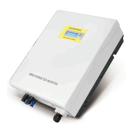
www.JFY-tech.com 1. OVERVIEW 1.1 M achine Overview Control and display panel RS232 outlet PV input AC terminals cover (AC terminals is inside) Front View Bottom View Fig.1 Overviews of inverter... - Page 7 Mounting frame 1pcs Mounting screws and blocks 6pcs Safety-lock screws 2pcs Socket head wrench 1pcs DC socket assembly 1set Special RS-232 cable 1pcs Instruction manual 1pcs Monitor software(CD) 1pcs Warranty sheet 1pcs SUNTWINS xxxxTL series include: SUNTWINS 3300TL ,SUNTWINS 4000TL,SUNTWINS 5000TL...
-
Page 8: Installation
www.JFY-tech.com 2. INSTALLATION WARNING: The electrical installation of SUNTWINS inverter must be performed in compliance with applicable local and national standards and laws. WARNING: The connection of SUNTWINS inverter to the AC grid must be performed only after receiving authorization from the utility that operates the grid. -
Page 9: Fixed On The Wall
Step3: Fix safety-lock screws at left side and right side as illustrated in Fig.5 with the attached socket head wench. Step4: Check the installation conditions. Fig.3 The size of mounting frame For SUNTWINS 3300TL, SUNTWINS 4000TL and SUNTWINS 5000TL... -
Page 10: System Diagram And Connection Label
www.JFY-tech.com Fig.4 Hang inverter to mounting frame Fig.5 Fix safety-lock screws The customer is encouraged to perform the following checks: Do not install the solar inverter on a gradient surface. Check the upper straps of solar inverter and ensure it to fit on to the bracket. ... - Page 11 www.JFY-tech.com The SUNTWINS series only operates when it is connected to the AC grid and can not operate as a stand-alone unit. The simplified connection diagram of the inverter is as follows. Fig.6 The PV system diagram A. PV Panels: Provide DC power to inverter. B.
-
Page 12: Connecting To The Ac Grid (Utility)
M ode l D i a m e t e r( m m ) C r o s s Ar e a ( m m A WG N o. 2.05 3.31 SUNTWINS 3300TL SUNTWINS 2.59 5.27 4000TL/5000TL 2 . 6 Co nne c ti ng to PV Pa ne l ( DC i np ut ) A. -
Page 13: Connecting To Pv Panel (Dc Input)
www.JFY-tech.com C. Open DC Switch and Connect the positive and negative terminals from the PV panel to DC switch, then to positive (+) terminals and negative (-) terminals on the solar inverter. Each DC terminal on inverter can withstand 20Adc. D. -
Page 14: Ac Output Protective Device
B. For model SUNTWINS 4000TL the AC output side should be in series a over current protective device which rated 25A, max rated breaking capacity 6KA C. For model SUNTWINS 3300TL the AC output side should be in series a over current protective device which rated 20A, max rated breaking capacity 6KA 3. -
Page 15: Operate The Function Key
www.JFY-tech.com 3 . 1 O p e rat e t he F unc t i o n Ke y To view the operating data of the inverter, you can press the Function Key. Of course, the data also will automatically and periodically display. To set different d isplay contrast and display language for the inverter, please carefully refert to the following chart. - Page 16 www.JFY-tech.com AS4777 SN:XXXXXXXXXXXXX Press function key Etoday=xx.xkWh Pac=xxxx.xW Press function key Etotal=xx.xkWh Pac=xxxx.xW Press function key Vac=xxx.xV Pac=xxxx.xW Press function key Vdc=xxx.x/xxx.xV Pac=xxxx.xW Press function key Iac=xx .xA Pac=xxxx.xW Fgrid=xx.xHz Pac=xxxx.xW Press function key SUNTWINS XXXXTL Ver E1.00 Press function key Date: xxxx-xx-xx Hour: xx:xx:xx Press function key...
-
Page 17: G E Ne Ra L L Cd Di Sp L A Y Inf O Rma T I O N
www.JFY-tech.com To lockup or unlock display message as follows: 3 . 2 G e ne ra l L CD Di sp l a y Inf o rma t i o n State Message In LCD STATE DISPLAY CONTENT COMMENTS Standby PV input voltage low W ait State W aiting... -
Page 18: Inverter Start-Up And Operation
www.JFY-tech.com Fgrid = xx.xHz The grid frequency Vdc=xxx.xV The PV input voltage AS4777 Comply with main standard English Current selected language Contrast x LCD Contrast Fgrid = xx Hz The grid frequency Note: 4.INVERTER START-UP AND OPERATION WARNING: Do not place any items on SUNTWINS inverter during operation. When the inverter is operating, do not touch the heat sink since some parts may become very hot. -
Page 19: Communications
www.JFY-tech.com Isolation error Insulation Problem of PV panel Ileak error GFCI Fault , leakage current is too high Grid fault Grid voltage/frequency is out of range Inverter fault Coherence error Con sistent Fault Over temperature Internal temperature abnormal Relay failure Output r elay Fault DCinj failure Output Current DC Offset too high... -
Page 20: Rj45 Connectors
www.JFY-tech.com two signal ones and one for ground connection. Fig. 11 The waterproof RJ45 socket and connectors for RS485 port To help installation, the inverter features two RJ45 sockets to separate input ethernet cable from output ethernet cable. 5 .2.2 RJ45 Connectors The RS485 serial connection, whether single unit or several inverters as daisy chain, can be performed by means of the RJ45 connectors (See Fig.11). - Page 21 www.JFY-tech.com RJ45 connectors may be used to connect a single SUNTWINS inverter or multiple SUNTWINS inverters daisy chained together. Up to 31 inverters can be daisy chained. Recommended maximum daisy chain length is 1000m. With multiple daisy-chained inverters, each unit will be automatically assigned a RS485 address with JFY monitoring software.
-
Page 22: Monitor Inverter
www.JFY-tech.com inverter in the chain. Even if there is only one inverter, the 120Ω terminal resistor is also necessary. 5.3 Monitor Inverter After RS232 or RS485 link is connected correctly, open JFY monitoring software “ JFY communicator”that is installed from the attached CD, the user can monitor the inverters. -
Page 23: Trouble Shooting
www.JFY-tech.com 7 . TROUBLE SHOOTING In most situations, the Inverter requires very little service. However, if Inverter is not able to work perfectly, please refer to the following instructions before calling your local dealer or service personnel. If any problems arise, the “ Alarm”LED on the front panel will be red and the LCD displays the relevant information. -
Page 24: Specifications
8. SPECIFICATIONS Model SUNTWINS 3300TL SUNTWINS 4000TL Parameter Input Data 3450W 4 160W Max. DC power 500V 500V Max. DC voltage MPPT operating 1 00V-450V 100V-450V voltage range Number of parallel inputs Number of MPP trackers Max. input current... - Page 25 www.JFY-tech.com Model SUNTWINS 5000TL Parameter Input Data 5200 W Max. DC power 500V Max. DC voltage MPPT operating 100V -450V voltage range Number of parallel inputs Number of MPP trackers Max. input current (total) Output Data Nominal AC output 4950W power Max.
-
Page 26: Jfy-Tech Warranty
www.JFY-tech.com 9. JFY-tech WARRANTY Warranty Policy: Warranty Period: The SUNTWINS Series PV Grid-tied inverters provided by Shenzhen JingFuYuan Tech. Co., LTD. (abbr. JFY-tech) have 60-month warranty period. The system accessories provided by JFY-tech have 24-month warranty period. Warranty Time Start: From the date that you get goods from our distributors. Warranty Evidence: The Purchasing Invoice from the distributors &... - Page 27 www.JFY-tech.com 11) The maintenance procedures relating to such product have not been observed or performed to an acceptable standard. 12) Force majeure (e.g., lightning, overvoltage, storm, fire) Claims that go beyond the rights cited in the warranty principles, in particular claims for compensation for direct or indirect damages arising from the defective device, for compensation for costs arising from disassembly and installation, or loss of profits are not covered by JFY-tech’...
-
Page 28: Jfy-Tech Contact Information
www.JFY-tech.com 10. JFY-tech CONTACT INFORMATION Shenzhen JingFuYuan Tech. Co., LTD. ADD: 5 Floor ,12 Block ,Nangang Second Industrial Park ,Nanshan District ,Shenzhen ,P.R.China Tel: +86-755-26632536 Fax: +86-755-26505986 Email: support@jfy-tech.com...
Need help?
Do you have a question about the SUNTWINS 3300TL and is the answer not in the manual?
Questions and answers
Hi I need to turn off the solar panel during cyclone weather, the instructions says 1. turn off Solar Main Switch in the Switchboard 2. turn off the DV 'PV Array Main Switch' (Left of inverter) - I can't seem to locate the main swtich
The Solar Main Switch for the JFY tech SUNTWINS 3300TL inverter is referred to as the "DC Switch" in the manual. It is located between the PV panels and the solar inverter. If the inverter has a model with the "-S" suffix, it includes an integrated DC switch on the PV input side. Additionally, the AC Switch is located between the AC Grid (Utility) and the solar inverter. These switches may consist of electrical breakers, fuses, and connecting terminals, and their installation should comply with local safety standards and be performed by a qualified technician.
This answer is automatically generated