Table of Contents
Advertisement
Available languages
Available languages
Quick Links
Advertisement
Table of Contents

Subscribe to Our Youtube Channel
Summary of Contents for RCF TTS36-A
- Page 1 OWNER MANUAL HIGH OUTPUT ACTIVE TTS36-A SUBWOOFER...
- Page 3 LANGUAGE ENGLISH ITALIANO...
-
Page 4: Safety Precautions
(wall, ceiling, structure, etc.), and the components used for attachment (screw anchors, screws, brackets not supplied by RCF etc.), which must guarantee the security of the system / installation over time, also considering, for example, the mechanical vibrations normally generated by transducers. -
Page 5: Operating Precautions
RCF S.p.A. will not assume any responsibility for the incorrect installation and / or use of this product. -
Page 6: Product Informations
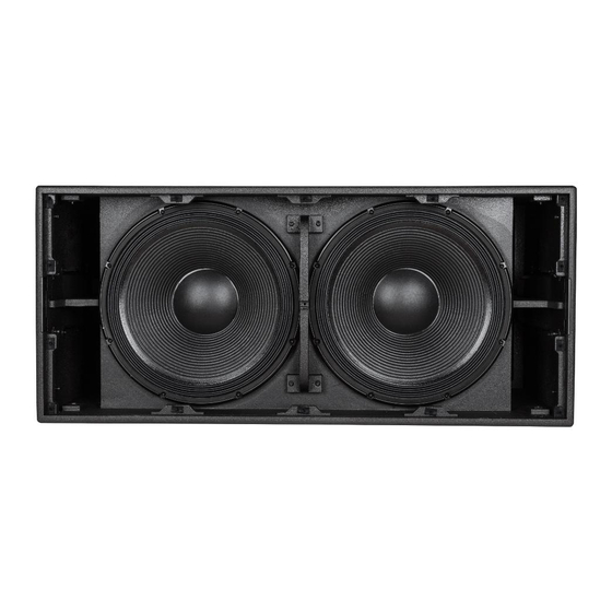
TTS36-A, HIGH OUTPUT SUBWOOFER TTS36-A, The TTS36-A is a high power, high output active subwoofer system that sets a new standard in HIGH OUTPUT the touring and theatre sound reinforcement. Each transducer has been specifically designed for SUBWOOFER the application. - Page 7 The TTS36-A amplifier section features: 2 x 2000 Watt digital amplifiers. PFC circuit. 7 x cooling speed controlled fans. Powercon AC input connector. Vibrostop floating aluminum panel. REAR PANEL MAIN SIGNAL XLR INPUT (BAL/UNBAL). The system accept female XLR input connectors and line-level signals from a mixing console or other signal source.
- Page 8 POWER MAIN SWITCH. The power switch turns the AC power ON and OFF. Make sure that the sensitivity is set to + 10 dBu when you turn on the speaker. AC POWERCON RECEPTACLE. RCF TT+ series uses a POWERCON locking 3-pole AC mains. Always use the specific power cord provided in the package.
- Page 9 CONNECTIONS The XLR connectors use the following AES standard: PIN 1 = GROUND (SHIELD) PIN 2 = HOT (+) PIN 3 = COLD (-) COLD BAL. XLR At this point you can connect the power supply cable and the signal cable, but before BEFORE TURNING ON turning on the speaker make sure that the volume control is at the minimum level (even THE SPEAKER...
- Page 10 BY-PASS SWITCH released (LED OFF): the system reads the input board and bypass the user setting eventually loaded ion the speaker (last configuration eventually saved). TTS36-A DEFAULT CONFIGURATION TTS36-A The TTS36-A factory default configuration (the configuration that the system reads if DEFAULT CONFIGURATION the BY-PASS switch is pressed) is the following: Sensitivity...
-
Page 11: Installation
WARNING: Always make sure that the maximum current requirement does not exceed WARNING the maximum admitted POWERCON current. In case of doubt call the closest RCF service centre. MAINS SUPPLY The system accept mains supply voltage115-230 (+15/-15%) V ~... - Page 12 Full compatibility with Socapex SL 419 Series. 13360145 AC POWER BOX 6XTTL55 EUROPEAN STAGE BOX TO POWER 6 TTL55-A LINE ARRAY MODULES OR 6 TTS36-A MODULES 1 piece for every 6 pieces of TTL55 and 1 piece for every 6 pieces of TTS56 SUB are suggested.
-
Page 13: Avvertenze Per La Sicurezza
Verificare inoltre l’idoneità del supporto (parete, soffitto, struttura ecc., al quale è ancorato il prodotto) e dei componenti utilizzati per il fissaggio (tasselli, viti, staffe non fornite da RCF ecc.) che devono garantire la sicurezza dell’impianto / installazione nel tempo, anche considerando, ad esempio, vibrazioni meccaniche normalmente generate da un trasduttore. - Page 14 L’installazione e l’utilizzo errati del prodotto esimono la RCF S.p.A. da ogni responsabilità. ATTENZIONE ATTENZIONE: per prevenire i rischi di fiamme o scosse elettriche, non esporre mai questo...
-
Page 15: Descrizione Generale
RCF TT+ offre soluzioni e strumenti di immediato utilizzo nel campo dei diffusori attivi ad alta definizione. -
Page 16: Pannello Posteriore
Selettore di by-pass delle impostazioni RDNet. Connettori di ingresso ed uscita RDNet. 4 LED di stato. La sezione di amplificazione del TTS36-A è dotata di: 2 amplificatori digitali da 2000 Watt. 2 circuiti di alimentazione dotati di circuito di correzione PFC. - Page 17 STATUS INDICATOR. L’indicatore di stato si accende con colore ARANCIONE se l’amplificatore principale evidenzia un malfunzionamento. Nel caso in cui il led STATUS si accenda spegnere e scollegare l’apparecchio e rivolgersi al CENTRO ASSISTENZA RCF più vicino. SIGNAL INDICATOR. Il led di segnale si accende con colore VERDE se è presente segnale audio all’ingresso XLR.
- Page 18 CONNESSIONI Il connettore di ingresso XLR segue il seguente standard AES: PIN 1 = TERRA (GROUND; SHIELD) PIN 2 = LATO CALDO (HOT; +) PIN 3 = LATO FREDDO (COLD; -) COLD BAL. XLR PRIMA DI ACCENDERE A questo punto potete inserire il connettore di alimentazione e il connettore di segnale, ma prima di accendere il diffusore assicuratevi che il controllo di volume sia al minimo sia sul IL DIFFUSORE diffusore che sulla sorgente sonora collegata al diffusore (che generalmente sarà...
- Page 19 (ultima configurazione eventualmente salvata). CONFIGURAZIONE DI DEFAULT TTS36-A CONFIGURAZIONE La configurazione di default del modulo TTS36-A (la configurazione che viene letta se DI DEFAULT TTS36-A RDNet non è presente ed il pulsante by-pass è premuto) è la seguente: Sensibilità...
-
Page 20: Installazione
ATTENZIONE: assicurarsi sempre che la richiesta massima di corrente non superi la corrente massima ammessa dai connettori POWERCON. In caso di dubbio contattare il centro assistenza RCF più vicino. TENSIONE DI ALIMENTAZIONE Il sistema accetta una tensione di alimentazione di 115-230 (+15/-15%) V ~... - Page 21 I seguenti accessori sono separatamente disponibili: 13360138 AC POWER CABLE 6XTTL55 POWER CABLE 1 pezzo ogni 6 moduli di TTL55-A o moduli TTS36-A. Completa compatibilità con Socapex Serie SL 419. 13360145 AC POWER BOX 6XTTL55 STAGE BOX EUROPEO PER ALIMENTARE 6 TTL55-A O 6 TTS36-A 1 pezzo ogni 6 moduli di TTL55-A o moduli TTS56-A.
-
Page 22: Specifications
± SPECIFICATIONS µ ÷ ACOUSTIC DATA Operating frequency range 30 - 120 Hz Max SPL 143 dB Crossover point 60 Hz/ 90 Hz TRANSDUCERS Low frequency 2 x 18” neodymium woofer, 4.5” voice coil AMPLIFIERS 2 x 2000 Watt digital amplifiers PFC switching power supply INPUTS Signal Input/Output... - Page 24 HEADQUARTERS: RCF S.p.A. Italy tel. +39 0522 274 411 e-mail: info@rcf.it RCF UK tel. 0844 745 1234 Int. +44 870 626 3142 e-mail: info@rcfaudio.co.uk RCF France tel. +33 1 49 01 02 31 e-mail: france@rcf.it RCF Germany tel. +49 2203 925370 e-mail: germany@rcf.it...
Need help?
Do you have a question about the TTS36-A and is the answer not in the manual?
Questions and answers