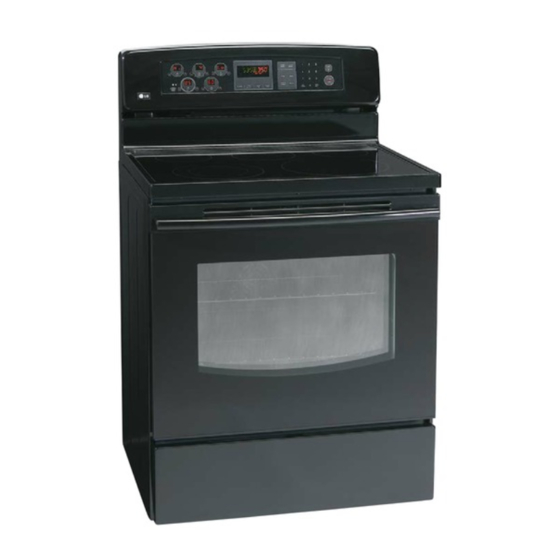
LG LRE30451 Service

LG LRE30451 Service

Electric range
Hide thumbs Also See for LRE30451:
Table of Contents

Advertisement

Quick Links

TRAINING MANUAL
ELECTRIC RANGE
LRE30451
LRE30755
Service
Digital Appliance

Advertisement

Table of Contents
loading

Summary of Contents for LG LRE30451

  • Page 1 TRAINING MANUAL ELECTRIC RANGE LRE30451 LRE30755 Service Digital Appliance...
  • Page 2 SAFETY PRECAUTIONS • Repairs of the appliance should be carried out by a licensed technician only. Incorrect repairs may result in dangerous situations. If you need repairs, contact an LG Service Center or your dealer. • If the power cord is defective, it must be replaced by a qualified service agent with a UL listed range cord.
  • Page 3: Table Of Contents

    TABLE OF CONTENTS GENERAL- - - - - - - - - - - - - - - - - - - - - - - - - - - - - - - - - - - - - - - - - - - - - - - - - - - - - - - - - - - - - - - - - - - - - - - - - - - - - - - - - - - - - - - - - - - - 1-1 ~ 1-4 •...
  • Page 4 (Page) COMPONENT TEST - - - - - - - - - - - - - - - - - - - - - - - - - - - - - - - - - - - - - - - - - - - - - - - - - - - - - - - - - - - - - - - - - - - - - - - - - - - - - 4-1 ~ 4-8 •...
  • Page 5: General

    GENERAL IMPOR ANT SAFETY INSTRUCTIONS IMPOR ANT SAFETY INSTRUCTIONS Read and follow all instructions before using your oven to prevent the risk of fire, electric shock, injury to person, or damage when using the range. This guide don’t cover all possible conditions that may occur. For further assistance contact your service agent or manufacturer.
  • Page 6 GENERAL IMPOR ANT SAFETY INSTRUCTIONS IMPOR ANT SAFETY INSTRUCTIONS SURFACE COOKING UNITS VENTILATING HOODS: • Clean Ventilating Hoods Frequently – Grease should not • Use Proper Pan Size – This appliance is equipped with one or be allowed to accumulate on hood or filter. more surface units of different sizes.
  • Page 7: Model & Serial Number Label And Tech Sheet Locations

    GENERAL MODEL & SERIAL NUMBER LABEL MODEL & SERIAL NUMBER LABEL AND TECH SHEET LOCA TIONS AND TECH SHEET LOCA TIONS The Model/Serial Number label and Tech Sheet locations are shown below. Model & Serial Number Location Tech Sheet Location (On Low Rear Cover)
  • Page 10: Using Your Range

    USING YOUR RANGE GENERAL INFORMA TION GENERAL INFORMA TION Rating Label Convection Bake / Roast Mode Upper element, lower element, Rear element(some Model numbers are recorded on the rating label. model) and fan operate during convection bake. Rating label is located on the lower front left corner Convection bake should be used for cooking of the oven frame.
  • Page 11 LRE30451 j j j j LRE30755...
  • Page 12 See the using the Self-Cleaning Oven section. 15. OVEN LIGHT PAD: Press to turn the oven light on or off. 16. DISPLAY Single surface units : Right Rear, Left Rear, Right Front Dual element: Left Front (LRE30451) Right (LRE30755) Warming Zone : Center Rear...
  • Page 13: To Turn On A Dual Surface Unit (Right Front)

    USING YOUR RANGE To turn on a single surface unit 4. TIMER ON/OFF (Right Rear, Left Rear, Left Front) TIMER Desired TIMER 1. Press ON/OFF pad for the desired element. ON/OFF time ON/OFF 2. Press ( ) pad to choose the desired setting. To cancel timer at any time, touch TIMER ON/OFF pad.
  • Page 14: Bake, Timed Bake, Delayed Timed Bake

    USING YOUR RANGE 5) BEEPER VOLUME 8. CONVECTION BAKE 1. Press OPTIONS pad 5 times CONV. Desired START 2. Press “1” pad for loud level, BAKE Temp. “2” pad for normal level, “3” pad for low level, 9. CONVECTION ROAST “4”...
  • Page 15: Warming Drawer

    USING YOUR RANGE ARMING DRA ARMING DRA NOTE: ONLY ON MODEL LRE30755 The rack can be used in 2 ways: To set the warming drawer control 1. Press the ON/OFF pad at the • In the upright position to allow low profile food WARMING DRAWER items to be placed both under and on top of the position.
  • Page 16: Component Access

    COMPONENT ACCESS This section instructs you on how to service each component inside the range. The components and their locations are shown below. COMPONENT LOCA TIONS COMPONENT LOCA TIONS Main PCB Cook Top Display PCB Cook Top Relay PCB Door Locking Motor &...
  • Page 17: Removing The Back, Control Cover And Key Membrane Assembly

    COMPONENT ACCESS REMOVING THE BACK, CONTROL COVER REMOVING THE BACK, CONTROL COVER AND KEY MEMBRANE ASSEMBL AND KEY MEMBRANE ASSEMBL 4. Remove the 3 screws from the rear control cover WARNING and remove the cover. 5. Remove 6 screws of PCB assembly and separate ELECTRICAL SHOCK HAZARD PCB assembly.
  • Page 18: Removeing The Control Power Supply And Power Control Board (Pcb)

    COMPONENT ACCESS REMOVING THE CONTROL POWER SUPPL REMOVING THE CONTROL POWER SUPPL AND POWER CONTROL BOARD (PCB) AND POWER CONTROL BOARD (PCB) 5. To remove the control power supply: WARNING a) Disconnect 2 connectors. b) Remove the two screws. ELECTRICAL SHOCK HAZARD Disconnect power before servicing the range.
  • Page 19 COMPONENT ACCESS REMOVING THE SURF ACE ELEMENTS REMOVING THE SURF ACE ELEMENTS AND THE CERAMIC GLASS COOKT AND THE CERAMIC GLASS COOKT Step. 5 WARNING Protect the cooktop surface ELECTRICAL SHOCK HAZARD and turn the assembly over. Disconnect power before servicing the range. Replace all panels before operating range.
  • Page 20 COMPONENT ACCESS REMOVING THE DOOR LA TCH & DOOR SWITCH REMOVING THE DOOR LA TCH & DOOR SWITCH b) Remove the door latch from the burner box WARNING and unhook the actuating rod. ELECTRICAL SHOCK HAZARD Unhook Disconnect power before servicing the range. Actuating Replace all panels before operating range.
  • Page 21: Removing The Broil Element

    COMPONENT ACCESS REMOVING THE BROIL ELEMENT REMOVING THE BROIL ELEMENT b) Pull the element forward so that you can WARNING access the terminals and disconnect the wires. ELECTRICAL SHOCK HAZARD Terminals Disconnect power before servicing the range. Replace all panels before operating range. Failure to do so can result in death or electrical shock.
  • Page 22: Removing The Bake Element

    COMPONENT ACCESS REMOVING THE HIDDEN BAKE ELEMENT REMOVING THE HIDDEN BAKE ELEMENT 1. Unplug range or disconnect power. 7. Bend the insulation glass fiber up. 2. Pull the range out of its mounting location so that you can access the rear of the unit. 3.
  • Page 23: Removing The Convection Element, Fan Blade And Fan Motor

    COMPONENT ACCESS REMOVING THE CONVECTION ELEMENT AN BLADE AND F AN MOT REMOVING THE CONVECTION ELEMENT AN BLADE AND F AN MOT NOTE: CONVECTION ELEMENT IS ONLY ON MODEL LRE30755 1. Disconnect power and remove oven racks. 8. To remove Fan motor assembly, disconnect wire connection and remove the three bracket 2.
  • Page 24: Removing The Oven Light & Socket Assembly

    COMPONENT ACCESS REMOVING THE OVEN LIGHT & SOCKET ASSEMBL REMOVING THE OVEN LIGHT & SOCKET ASSEMBL CAUTION WARNING Be careful not to scratch or chip the oven liner ELECTRICAL SHOCK HAZARD paint when you remove the oven light socket in Disconnect power before servicing the range.
  • Page 25: Removing The Latch Drive Assembly

    COMPONENT ACCESS REMOVING THE LA TCH DRIVE ASSEMBL REMOVING THE LA TCH DRIVE ASSEMBL DOOR LOCKING MECHANISM WARNING The door lock assembly is located at the back side ELECTRICAL SHOCK HAZARD of range. The structural elements are as below. Disconnect power before servicing the range. Replace all panels before operating range.
  • Page 26: Removing The Oven Temperature Sensor

    COMPONENT ACCESS REMOVING THE OVEN TEMPERA TURE SENSORS REMOVING THE OVEN TEMPERA TURE SENSORS 5. To remove an oven temperature sensor, WARNING disconnect the connector from the main harness and remove the two mounting screws in oven ELECTRICAL SHOCK HAZARD cavity.
  • Page 27 COMPONENT ACCESS REMOVING THE W ARMING DRA WER ELEMENT REMOVING THE W ARMING DRA WER ELEMENT & TEMPERA TURE SENSOR & TEMPERA TURE SENSOR NOTE: ONLY ON MODEL LRE30755 To remove the warming drawer element: WARNING 1. Remove the two bottom bracket screws ELECTRICAL SHOCK HAZARD Disconnect power before servicing the range.
  • Page 28: Removing & Replacing The Lift-Off Oven Door

    COMPONENT ACCESS REMOVING & REPLACING THE LIFT -OFF OVEN DOOR REMOVING & REPLACING THE LIFT -OFF OVEN DOOR To replace the door: CAUTION Step. 1 The door is very heavy. Be careful when Firmly grasp both removing and lifting the door. Do not lift the door sides of the door by the handle.
  • Page 29: Removing The Oven Door Handle & Glass

    COMPONENT ACCESS REMOVING THE OVEN DOOR HANDLE & GLASS REMOVING THE OVEN DOOR HANDLE & GLASS 6. To remove the door handle & trim (for stainless model) WARNING a) Remove the 4 door handle screws and lift the door handle off door trim and slide up the door handle. ELECTRICAL SHOCK HAZARD Disconnect power before servicing the range.
  • Page 30 COMPONENT ACCESS 7. To remove a hinge hanger assembly: d) Lift the inner oven door glass and bracket a) Remove the 2 top liner screws assembly out of the door liner. (See step 3 on page 3-14) b) Place the door liner assembly on a padded work surface with the hinge hangers over the edge.
  • Page 31: Removing The Oven Door Gasket

    COMPONENT ACCESS REMOVING THE OVEN DOOR GASKET REMOVING THE OVEN DOOR GASKET 3. Pull the ends of the gasket out of the liner holes. WARNING Liner Hole ELECTRICAL SHOCK HAZARD Disconnect power before servicing the range. Replace all panels before operating range. Failure to do so can result in death or electrical shock.
  • Page 32: Removing A Side Panel

    COMPONENT ACCESS REMOVING A SIDE P ANEL REMOVING A SIDE P ANEL 7. Remove the two screws from the left or right side WARNING panel. ELECTRICAL SHOCK HAZARD Disconnect power before servicing the range. Replace all panels before operating range. Failure to do so can result in death or electrical shock.
  • Page 33: Component Test

    COMPONENT TEST Before testing any of components, perform the following checks: NOTE: 1. The most common cause for control failure is corrosion on connectors. Therefore, disconnecting and reconnecting wires will be necessary throughout test procedures 2. ALL units in the first few days of use should be checked for mis-wiring or loose connections 1.
  • Page 34: Door Locking Motor

    Components Test procedures Results Normal: Approximately Door locking Motor 1. Refer to page 3-10 for the servicing procedure 2.6 kΩ ± 10% 2. Measure the resistance If not replace (Multiple meter scale: R x 1000) Abnormal: Infinite(open) below 5Ω (shorted) Door latch Door latch Micro Switch...
  • Page 35: Oven Sensor

    Components Test procedures Results Normal: Approximately Oven Sensor 1. Refer to page 3-11 for the servicing procedure 1.09 kΩ ± 10% 2. Measure the resistance after cooling down If not replace (Multiple meter scale: R x 1000) NOTE: Ω Value was tested at room temperature (77F/25˚C) NOTE: Oven sensor is so sensitive to temperature...
  • Page 36: Broil Element

    Components Test procedures Results Normal: Approximately Broil element 1. Refer to page 3-6 for the servicing procedure 14 Ω ± 10% 2. Measure the resistance after cooling down If not replace (Multiple meter scale: R x1) NOTE: Ω Value was tested at room temperature (77F/25˚C) Be careful the element is...
  • Page 37: Oven Lamp

    Components Test procedures Results Normal: Below 5 Ω. Oven lamp 1. Measure the resistance after cooling down If not replace (Multiple meter scale: R x1)
  • Page 38: Single Surface Unit(Lf, Lr, Rr)

    Components Test procedures Results Single surface units: 1. Refer to page 3-4 for the servicing procedure Left Front (LF), 2. Set the Multiple meter scale to the R x 1 Left Rear (LR) 3. Disconnect wires from cook-top elements 4. Touch the ohmmeter test leads to the element Right Rear(RR) terminal and 1A.
  • Page 39: Warming Zone

    Components Test procedures Results Center Rear(CR) 1. Refer to page 3-4 for the servicing procedure Element 2. Set the Multiple meter scale to the R x 1 ;Warming Zone 3. Disconnect wires from CR elements 4. Touch the ohmmeter test leads to the element terminal and 1A.
  • Page 40: Dual Surface Unit(Rf)

    Components Test procedures Results Dual surface element 1. Refer to page 3-4 for the servicing procedure : Right Front(RF) 2. Set the Multiple meter scale to the R x1 3. Disconnect wires from cook-top elements 4. Touch the ohmmeter test leads to the (E1 & 1A) and (E2 &...
  • Page 41: Composition Of Control

    COMPOSITION OF CONTROL Main PCB ( P/N : 6871W1N009A) Front Front Back Back Cook top display PCB ( P/N : 6871W1N010A) Controller assembly Front Back Cook top relay PCB ( P/N : 6871W1N011A) Key pad assembly Front Front Back Oven relay PCB ( P/N : 6871W1N012A) Back Front Back...
  • Page 42: Main Pcb

    COMPOSITION OF CONTROL Main PCB Main PCB P/N : 6871W1N009A Main function ▶ Supply a DC power source (GND, -5V, -12V(Vry(oven heater switching)), -30V) ▶ Oven heater control (DLB / Broil / Bake / Warming drawer / convection) ▶ Oven display control ▶...
  • Page 43: Cook-Top Display Pcb

    COMPOSITION OF CONTROL Cook-top display PCB Cook-top display PCB P/N : 6871W1N010A Main function ▶ Single radiant surface elements -Right Rear, Left Rear, Left Front- power level indication ▶ Dual radiant surface elements -Right Front inner, outer- power level indication ▶...
  • Page 44: Cook-Top Relay Pcb

    COMPOSITION OF CONTROL Cook-top relay PCB Cook-top relay PCB P/N : 6871W1N011A Main function ▶ Supply a DC power source (GND, -12V (Vry(cooktop heater switching voltage)) ▶ Single Radiant Surface Elements -Right Rear, Left Rear, Left Front - on/off, power level relay switching ▶...
  • Page 45 CHECKING FLOW CHART BY FAILURE MODE No display (No power) Blank display Enter key input Check the thermal fuse Some beep (See the page 3-1) sound? Check AC input voltage of Main PCB Cook-top display -Main PCB CN2 (pin 1 and 3) blank? (Go to page 6-4) Check voltage –...
  • Page 46: Failure Mode Flow Chart

    FAILURE MODE FLOW CHART No display (No power) Blank display Enter key input Check the thermal fuse Some beep (See the page 3-1) sound? Check AC input voltage of Main PCB Warming drawer -Main PCB CN2 (pin 1 and 3) display blank? (Go to page 6-4) Check voltage –...
  • Page 47: No Display (No Power)

    FAILURE MODE FLOW CHART No display (No power) Blank display Enter key input Check the thermal fuse Some beep (See the page 3-1) sound? Check AC input voltage of Main PCB Oven display blank? -Main PCB CN2 (pin 1 and 3) (Go to page 6-4) Replace the main PCB(009A)
  • Page 48 FAILURE MODE FLOW CHART No display (No power) Check the harness of between L1~N Is it 120V AC? Normal? Disconnect power Replace the defective harness Check the power transformer (Refer to the below) Primary S3 S2 S1 Secondary Fig.1 Side Lead Color DCR(Ω) black ~ white...
  • Page 49: Oven Does Not Heat

    FAILURE MODE FLOW CHART Oven does not heat Code Error mode Operation Times/sampling No heating If current oven temperature does not exceed 150˚F and During cook less than start temperature over 5 minutes on preheating, where door is closed. (except proof and cook & warm ) No Heating(Main Oven) Disconnect power Check for loose connections at bake, broil,...
  • Page 50 FAILURE MODE FLOW CHART Oven does not heat Normal? Replace the bake heater Check the broil heater (measure the resistance after cooling down) Normal: approximately 14Ω Normal? Replace the broil heater Check the convection heater (measure the resistance after cooling down) Normal: approximately 17Ω...
  • Page 51 FAILURE MODE FLOW CHART Oven does not heat Check for loose oven sensor connector Normal? Reconnect Check the oven sensor (measure the resistance after cooling down) Normal: approximately 1.09kΩ Normal? Replace the oven sensor Replace the oven relay PCB (012A) Normal? Replace the main PCB(009A) For further check of main PCB...
  • Page 52: Cook-Top Does Not Heat

    FAILURE MODE FLOW CHART Cook-top does not heat No heating (All or a part of cook-top heaters) Disconnect power Check for loose connection at board (011B PCB) to cook top heaters. Normal? Reconnect. If defective harness, replace or fix Check for loose connector (main PCB(009A) CN9 and CN16) Continued on the next page...
  • Page 53 FAILURE MODE FLOW CHART Cook-top does not heat Normal? Reconnect. Remove the cook-top relay PCB(011A) harness and pull the cook-top relay PCB(011A) forward from the PCB case Inspect the cook-top relay PCB(011A) Wide pattern(Live part) blown out pin to pin short or connector harness damaged Repairable Normal? by yourself?
  • Page 54: Oven Lamp Does Not Operate

    FAILURE MODE FLOW CHART Oven lamp does not operate Oven lamp does not operate Disconnect power Check for loose connection of oven lamp terminal and harness Normal? Reconnect Check for loose connector (main PCB CN1) If defective harness, replace or fix Normal? Reconnect Check the oven lamp (measure the resistance)
  • Page 55: No Key Input

    FAILURE MODE FLOW CHART No key input Key does not input Reconnect the main PCB connector CN11 and CN20 more than two times Normal? Some keys or All keys? Some Replace the main PCB(009A) Replace the main PCB Normal? Replace the keypad assembly 6-11...
  • Page 56: Failure Codes

    FAILURE CODES DISPLAY CAUSE CORRECTIVE ACTION WARNING SHOWS Main oven A. Perform step 1 through 2 above • Disconnect power supply cord from the outlet heating B. Open the back panel and check continuity of the before servicing error sensor, heater (bake, broil) and Control(PCB) C.
  • Page 57: F-Code Flow Chart

    F-CODE FLOW CHART Key short error F-1 error Code Error mode Operation Times/sampling Key shorted If a key pad is continuously short for 60 seconds. Key short error (F-1) Plugged out the power, remove keypad-tail and check F-1 error recur or not, after plugging in the power recur? Disconnect power...
  • Page 58 F-CODE FLOW CHART Door lock system error F-2 error Code Error mode Operation Times/sampling Door Lock Fail In case of Door Lock Failure → Just after self-clean start, the door lock motor starts to rotate. During that time if the door lock switch does not operate properly after rotating twice, then supervising circuit detects a Door Lock failure and the F-2 error code appears.
  • Page 59: Error

    F-CODE FLOW CHART Door lock system error F-2 error Normal? Replace the micro switch Check the door locking motor (measure the resistance) normal: approximately 2.6kΩ abnormal: infinite or below 5 Ω Normal? Replace the door locking motor Check for loose connector (Front) (main PCB CN4) Front Normal? Reconnect...
  • Page 60: Error

    F-CODE FLOW CHART Door lock system error F-2 error Inspect connector pin solder of CN4 (Back) (main PCB CN4) Back ※ If pin solder is cracked, repair and re-use Cracked? Replace Repair and fix...
  • Page 61: Error

    F-CODE FLOW CHART Main oven sensing error F-3, F-4 error Code Error mode Operation Times/sampling Opened Sensor Oven Thermistor remains open for over During cook 1 min, after cook starts Shorted Sensor Oven Thermistor is short for over 1 min During cook after cook starts Main oven sensing failed...
  • Page 62 F-CODE FLOW CHART Main oven sensing error F-3, F-4 error Check for loose connector. (Front) (main PCB CN6) Check for loose connector. (main PCB CN6) and look for harness terminals damaged or not Reconnect and Normal? replace the bad harness Remove the main PCB (009A) harness and pull the PCB (009A) forward from the PCB case Inspect connector pin solder of CN6 (Back) (main PCB CN6)
  • Page 63 F-CODE FLOW CHART Warming drawer sensing error F-5, F-6 error Code Error mode Operation Times/sampling Shorted Sensor Warm Drawer Thermistor short Over 1 min after warm During operate drawer operates Warm Drawer Thermistor open Over 1 min after warm During operate Opened Sensor drawer operates Warming drawer sensing failed...
  • Page 64 F-CODE FLOW CHART Warming drawer sensing error F-5, F-6 error Check for loose connector. (Front) (main PCB CN5) Check for loose connector. (main PCB CN5) and look for harness terminals damaged or not Normal? Reconnect and replace the bad harness Remove the main PCB(009A) harness and pull the PCB(009A) forward from the PCB case...
  • Page 65 F-CODE FLOW CHART Oven too hot error F-9 error Code Error mode Operation Times/sampling Oven hot Oven temperature is over 650˚F During cook continuously during 2 minutes on cooking. (Not self clean mode) Oven is too hot (F-9) Disconnect power / Remove the oven relay PCB (012A) harness and pull the oven relay PCB (012A) forward from case Check for a welded bake relay.
  • Page 66 F-CODE FLOW CHART Oven too hot error F-9 error Check for a welded broil relay. (measure the resistance) Welded Normal Continuity Infinite Normal? Replace the oven relay PCB(012A) Replace the main relay PCB(009A) 7-10...
  • Page 67: Appendix A (Schematic Diagram Of Pcb)

    APPENDIX A (SCHEMATIC DIAGRAM OF PCB)
  • Page 68: Trouble Shooting

    TROUBLE SHOOTING PROBLEMS POSSIBLE CAUSES & FAULTS SOLUTIONS Oven not operating. • Bad power control board (PCB) • Test and/or replace PCB © Refer to the page 6-1~6-4 • Power outage • Verify power is present at unit. • Verify that the circuit breaker is not tripped •...
  • Page 69 TROUBLE SHOOTING PROBLEMS POSSIBLE CAUSES & FAULTS SOLUTIONS Electronic timer will not • Failed main power control board • Replace power control board(PCB) accept Programming. Electronic timer will not • Failed main power control board • Replace power control board(PCB) accept Programming.
  • Page 70 TROUBLE SHOOTING PROBLEMS POSSIBLE CAUSES & FAULTS SOLUTIONS Oven door sagging on one • Hinge loose or out of position to • Adjust hinges or replace hinges side oven liner Door does not close • Broken or misadjusted door spring •...
  • Page 71: Schematic Diagram

    SCHEMATIC DIAGRAM For Model: LRE30755SW / SB / ST NOTE:Schematic diagram shows door WARNING switch In the cook position with the oven POWER MUST BE door open and elements off. DISCONNECTED BEFORE SERVICING THE APPLIANCE RADIANT COOK-TOP Wattage RR:1200W LR:1200W LF:2500W RF(Right Front) :1700W(inner)
  • Page 72: Strip Circuits

    STRIP CIRCUITS STRIP CIRCUITS Complete the following steps before checking electric oven circuit : 1.Check the line voltage, household fuse or circuit breaker. 2.Check for loose wiring or mis-wiring within electric range. NOTE: The following individual circuits are for use in diagnosis, and are shown in the ON position. For Model: LRE30755SW / SB / ST BAKE / COOK &...
  • Page 73 For Model: LRE30755SW / SB / ST WARMNING DRAWER SELF CLEANING 10-3...
  • Page 74 For Model: LRE30755SW / SB / ST CLOCK DISPLAY ON CONV. BAKE / CONV. ROAST CR (Warming Zone) 10-4...
  • Page 75 For Model: LRE30755SW / SB / ST RR Cook-top Element LR Cook-top Element LF Cook-top Element RF Cook-top Element 10-5...
  • Page 76: Exploded View

    #EV# EXPLODED VIEW INTRODUCTION (I) For Model: LRE30451, LRE30755 CONTROLLER PARTS COOKTOP PARTS DOOR PARTS CAVITY PARTS DRAWER PARTS 11-1...
  • Page 77 #EV# INTRODUCTION (II) For Model: LRE30455, LRE30755 CONTROLLER PARTS COOKTOP PARTS DOOR PARTS CAVITY PARTS DRAWER PARTS 11-2...
  • Page 78 #EV# DOOR PARTS (I) For Model: LRE30455, LRE30755 13581A 162081 WSZ218 13213A 149802 149801 162082 14810Q WTT025 WSZ222 148901 14810D WTT025 WSZ002 WTP028 WTT034 WTT021 WTT021 WTP028 WTT025 13806D WTT034 162083 14775A WTT025 149803 149804 WTT025 14775A 162082 13550C 149804 148902 13650A 11-3...
  • Page 79 #EV# DOOR PARTS (II) For Model: LRE30455, LRE30755 13581A WSZ218 162081 13213A 14810Q 148901 WTT025 WSZ222 14775A WTT034 WTT034 WTT025 WTT025 WSZ002 162083 149801 14775A WTT025 149801 13650A 11-4...
  • Page 80 #EV# CONTROLLER PARTS For Model: LRE30455, LRE30755 23808A 24781M WTP013 268711 249301 33920P 249303 WTP013 26170G 268712 WTP013 249302 268713 23551E WTT021 23572A 24790A WTT021 249802 34930W 249801 11-5...
  • Page 81 #EV# COOKTOP PARTS For Model: LRE30455, LRE30755 368771 368772 33301A 335303 33920P 335302 33920P 335304 335301 335303 34970A WSZ003 WTT018 349802 34970A WTT018 WTT024 34790A 349801 WTT024 349801 WTT030 11-6...
  • Page 82 #EV# DRAWER PARTS For Model: LRE30755SW / SB / ST 84818S 84870E WSZ225 WTT024 84870B 83212D WTT052 84818S 83720D 84980D WTT034 WTT034 WTT052 868771 WTT025 13650A 84980D WTT024 85012D 83550W WTP013 WTP013 86322D 84870C 834461 WTT030 834462 83550H 84818D 549803 85300D 848101 549803...
  • Page 83 #EV# CAVITY PARTS For Model: LRE30755SW / SB / ST 33808A 568772 54811A 33808B 54270A 56549A WWP008 WSZ221 34930W 549802 WNH002 55233A 55012A 36549C 53720A WTT034 WNH201 548101 55231C 55900C 568711 SPEC: 353002 120V, 40W 549801 WSZ221 WSZ219 WSZ221 WNZ022 56913A 548102 WTT030...
  • Page 84 #EV# DRAWER PARTS For Model: LRE30451SW / SB / ST 84870E 84818S WTP028 WTT024 84870B 83212D 84818S 83720D WTT025 WTT024 85012D 83550W WTP013 WTP013 84870C 834461 WTT030 834462 84818D 549803 549803 WTT030 84810D 83302D 83302D 847781 11-7...
  • Page 85 #EV# CAVITY PARTS For Model: LRE30451SW / SB / ST 33808A 54811A 568772 33808B 54270A 56549A WWP008 WSZ221 34930W 549802 WNH002 55233A 55012A 36549C 53720A WNH201 WTT034 548101 55231C 55900C 568711 SPEC: 353002 120V, 40W 549801 WSZ221 WSZ219 WSZ221 WNZ022 56913A 548102 WTT030...
  • Page 86 PARTS LIST Designator Model Factory Model_Suffix LRE30451SB LFRF0222_ABKELGA LRE30451ST LFRF0222S_ASTELGA LRE30451SW LFRF0222_AWHELGA LRE30755SB LCRF0222_ABKELGA LRE30755ST LCRF0222S_ASTELGA LRE30755SW LCRF0222_AWHELGA Please Note: Standard hardware items (screws, nuts, etc.) are informational listings only. They are not stocked items. Model Loc No. Part No Description Designator ABCDEF...
  • Page 87 Model Loc No. Part No Description Designator 353003 5300W1S028A HEATER, SHEATH, 120V 60HZ 800W 368771 6877W1N018A HARNESS, HEATER 368771 6877W1N034A HARNESS, HEATER 368772 6877W1N019A HARNESS, HEATER 368772 6877W1N035A HARNESS, HEATER ABCDEF 466001 6600R000082 SWITCH, TACT, 120VDC 4A 150 DEGREE ABCDEF 539201 3920W0N001A PACKING, SEAL, GLASS TUBE (GASKET) DIA.
  • Page 88 Model Loc No. Part No Description Designator 24781M 4781W0M070Q CONTROLLER ASSEMBLY, KEY PAD, STAINLESS 24781M 4781W0M070R CONTROLLER ASSEMBLY, KEY PAD, WHITE 24781M 4781W0M070S CONTROLLER ASSEMBLY, KEY PAD, BLACK 24781M 4781W0M070T CONTROLLER ASSEMBLY, KEY PAD, STAINLESS ABCDEF 24790A 4790W0N002B BARRIER, T0.6 CONTROLLER, CERAMIC COATED XFMR, POWER, 120V 60HZ DC15V/600MA AC4.7V/330MA 26170G 6170W1G035A...
  • Page 89 Model Loc No. Part No Description Designator 84980D 4980W1N023C SUPPORTER, DRAWER (SILVER) 84980D 4980W1N023F SUPPORTER, DRAWER WH HANDLE 85012D 5012W0N001A INSULATOR, T0.8 5.4CU. FT WOOL, LOWER 85012D 5012W0N001B INSULATOR, T0.8 5.4CU. FT WOOL, LOWER 85300D 5300W1S027A HEATER, SHEATH, 240V 60HZ 600W 86322D 6322A00023B THERMISTOR, NTC, 75C-7.214KOHM...

This manual is also suitable for:

Lre30755

Table of Contents