Table of Contents
Advertisement
Quick Links
Advertisement
Table of Contents

Subscribe to Our Youtube Channel
Summary of Contents for Patton SmartNode 4950
- Page 1 For Quick Start Installation SmartNode 4950 Series Multi-Port T1/E1/PRI VoIP Enterprise Gateway Router User Manual Sales Office: +1 (301) 975-1000 Technical Support: +1 (301) 975-1007 E-mail: support@patton.com WWW: www.patton.com Part Number: 07MSN4950-GS, Rev. B Revised: February 7, 2012...
- Page 2 Under no condition shall Patton Electronics be liable for any damages incurred by the use of this product. These damages include, but are not limited to, the following: lost profits, lost savings and incidental or consequential damages arising from the use of or inability to use this product.
-
Page 3: Summary Table Of Contents
Initial configuration ............................27 G.SHDSL Basic Configuration ........................36 Contacting Patton for assistance ........................41 Compliance information ..........................44 Specifications ..............................48 Cabling ................................. 55 Port pin-outs ..............................60 SmartNode 4950 factory configuration ......................63 End user license agreement ........................... 65... -
Page 4: Table Of Contents
Safety when working with electricity .......................11 General observations ............................12 Typographical conventions used in this document....................12 General conventions ............................12 General information ............................13 SmartNode 4950 overview ............................14 SN4950 model codes ............................15 SN4951 model codes ............................15 SmartNode 4950 rear panel...........................16 SmartNode 4950 front panel..........................18 Applications overview............................ - Page 5 Contacting Patton for assistance ........................41 Introduction ................................42 Contact information..............................42 Patton support headquarters in the USA ......................42 Alternate Patton support for Europe, Middle East, and Africa (EMEA) ............42 Warranty Service and Returned Merchandise Authorizations (RMAs)..............42 Warranty coverage ............................42 Out-of-warranty service ..........................43 Returns for credit ............................43...
- Page 6 SmartNode 4950 User Manual Table of Contents CE Declaration of Conformity ..........................47 Authorized European Representative ........................47 Specifications ..............................48 Voice connectivity ..............................49 Data connectivity ..............................49 Voice processing (signalling dependent) ........................49 Fax and modem support............................49 Voice signalling ..............................50 Voice routing—session router..........................50 services................................50...
-
Page 7: List Of Figures
SmartNode 4950 front panel ........ -
Page 8: List Of Tables
SmartNode 4950 models with integrated G.SHDSL interface ........ -
Page 9: About This Guide
About this guide This guide describes the SmartNode 4950 hardware, installation and basic configuration. For detailed software configuration information refer to the SmartWare Software Configuration Guide and the available Configura- tion Notes. Audience This guide is intended for the following users: •... -
Page 10: Precautions
SmartNode 4950 User Manual Precautions Notes, cautions, and warnings, which have the following meanings, are used throughout this guide to help you become aware of potential problems. Warnings are intended to prevent safety hazards that could result in per- sonal injury. Cautions are intended to prevent situations that could result in property damage or impaired functioning. -
Page 11: Safety When Working With Electricity
SmartNode 4950 User Manual Safety when working with electricity • Do not open the device when the power cord is connected. For systems without a power switch and without an external power adapter, line volt- WARNING ages are present within the device when the power cord is connected. -
Page 12: General Observations
SmartNode 4950 User Manual Always follow ESD prevention procedures when removing and replacing cards. CAUTION Wear an ESD-preventive wrist strap, ensuring that it makes good skin contact. Connect the clip to an unpainted surface of the chassis frame to safely channel unwanted ESD voltages to ground. -
Page 13: General Information
Chapter 1 General information Chapter contents SmartNode 4950 overview ............................15 SN4950 model codes ............................16 SN4951 model codes ............................16 SmartNode 4950 rear panel...........................17 SmartNode 4950 front panel..........................19... -
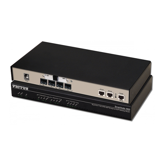
Page 14: Smartnode 4950 Overview
PSTN and VoIP networks. Figure 1. SmartNode 4950 The SmartNode 4950 Gateway-Router performs the following major functions: • Up to 120 VoIP Calls—Up to 120 simultaneous voice or T.38 fax calls with one to four T1/E1/PRI ports and dual Gigabit Ethernet ports. -
Page 15: Sn4950 Model Codes
1 • General information SN4950 model codes The SmartNode 4950 series consists of several models. They differ in the number of PRI ports and voice chan- nels supported. All models come equipped with two 10/100/1000Base-T Ethernet ports. The SmartNode 4950 PRI ports and voice channels are listed in table 2. -
Page 16: Smartnode 4950 Rear Panel
SmartNode 4950 User Manual 1 • General information SmartNode 4950 rear panel The SmartNode 4950 rear panel ports are described in table 0 /3 0 /2 0 /1 0 /0 0 /1 0 /0 o le Power SN4950/1E30V ETH 0/1... -
Page 17: Rear Panel Ports
SmartNode 4950 User Manual 1 • General information Table 4. Rear panel ports Port Description WAN ETH 0/0 Auto-MDX Gigabit-Ethernet port, RJ-45 (see ), connects the unit to an Ethernet figure 2 WAN device (for example, a cable modem, DSL modem, or fiber modem). Note: Only full duplex modes are supported. -
Page 18: Smartnode 4950 Front Panel
SmartNode 4950 User Manual 1 • General information SmartNode 4950 front panel Figure 3 shows SmartNode 4950 front panel LEDs, the LED definitions are listed in table lt i- r t T 1 /E 1 /P te r p r is... -
Page 19: Sn4950 Front And Rear Panel Leds
SmartNode 4950 User Manual 1 • General information Table 5. SN4950 Front and Rear panel LEDs Description Note If an error occurs, all LEDs will flash once per second. Power When lit, indicates power is applied. When lit, the unit is in normal operation. Flashes once per second during boot (startup). -
Page 20: Applications Overview
Chapter 2 Applications overview Chapter contents Introduction ................................21 Application—Multi-service ISDN Internet telephony IAD ...................21... -
Page 21: Introduction
Application—Multi-service ISDN Internet telephony IAD The SmartNode 4950 Series can be used to make and receive calls to and from the public ISDN network and Internet Telephony services on any ISDN Terminal (Phone or PBX) (see figure 4). -
Page 22: Smartnode Installation
Chapter 3 SmartNode installation Chapter contents Planning the installation............................23 Site log ................................23 Network information ............................23 Network Diagram ............................23 IP related information .............................23 Software tools ..............................24 AC Power Mains .............................24 Location and mounting requirements ......................24 Installing the gateway router..........................24 Placing the SmartNode ...........................24 Installing cables ...............................24... -
Page 23: Planning The Installation
24 to install the device. Site log Patton recommends that you maintain a site log to record all actions relevant to the system, if you do not already keep such a log. Site log entries should include information such as listed in table Table 6. -
Page 24: Software Tools
If you suspect that your AC power is not reliable, for example if room lights flicker often or there is machinery with large motors nearby, have a qualified professional test the power. Patton recommends that you include an uninterruptible power supply (UPS) in the installation to ensure that VoIP service is not impaired if the power fails. -
Page 25: Connecting The Pri
Connecting the 10/100/1000Base-T Ethernet LAN and WAN cables The SmartNode 4950 has automatic MDX (auto-crossover) detection and configuration on all Ethernet ports. Any of the ports can be connected to a host or hub/switch with a straight-through or cross-over wired cable. -
Page 26: Connecting The Power Supply
SmartNode 4950 User Manual 3 • SmartNode installation Connecting the power supply Do not connect power to the AC Mains at this time. • The external power adapter shall be a listed Limited Power • WARNING CAUTION Source. • The 4950 external power supply automatically adjusts to accept an input voltage from 100 to 240 VAC (50/60 Hz). -
Page 27: Initial Configuration
Chapter 4 Initial configuration Chapter contents Introduction ................................28 1. Connecting the SmartNode to your laptop PC....................28 2. Configuring the desired IP address ........................29 Factory-default IP settings ..........................29 Login ................................29 Changing the WAN IP address ........................29 3. Connecting the SmartNode to the network .......................30 4. -
Page 28: Introduction
CAUTION mechanical serviceability. The SmartNode 4950 Series is equipped with Auto-MDX Ethernet ports, so you can use straight-through cables for host or hub/switch connections (see figure 0/ 3... -
Page 29: Configuring The Desired Ip Address
SmartNode 4950 User Manual 4 • Initial configuration 2. Configuring the desired IP address Factory-default IP settings The factory default configuration for the Ethernet interface IP addresses and network masks are listed in table Both Ethernet interfaces are activated upon power-up. LAN interface ETH 0/1 (LAN) provides a default DHCP server, the WAN interface uses DHCP client to automatically assign the IP address and network mask. -
Page 30: Connecting The Smartnode To The Network
In general, the SmartNode will connect to the network via the WAN (ETH 0/0) port. This enables the Smart- Node to offer routing services to the PC hosts on LAN (ETH 0/1) port. The SmartNode 4950 Series is equipped with Auto-MDX Ethernet ports, so you can use straight-through or crossover cables for host or hub/... -
Page 31: Loading The Configuration (Optional)
Guide.) 4. Loading the configuration (optional) Patton provides a collection of configuration templates on the support page at www.patton.com/smart- node—one of which may be similar enough to your application that you can use it to speed up configuring the SmartNode. -
Page 32: Bootloader
SmartNode via one of the Ethernet interfaces, or open a CLI session via the console port (if available on the SmartNode). The login display will appear. Using the credentials admin / patton , log in to the SmartNode. The following prompt will be displayed: RedBoot>... - Page 33 SmartNode 4950 User Manual 4 • Initial configuration Step Command Purpose RedBoot> load -r -v -h host -b Downloads an application image into the vola- base_address file_name tile memory (RAM) from where the SmartNode could directly execute it. host: IP address of the TFTP server base_address: memory location where to store the application image.
-
Page 34: Load A New Application Image (Smartware) Via The Serial Link
SmartNode 4950 User Manual 4 • Initial configuration Delete image 1 - continue (y/n)? y ... Erase from 0x60030000-0x601cc974: ......RedBoot> fis create Use address 0x01800100, size 1684402 ? - continue (y/n)? y ... Erase from 0x60030000-0x601cb3ba: ......Program from 0x00011eec-0x00011ef4 at 0x60030000: . -
Page 35: Additional Information
SmartNode 4950 User Manual 4 • Initial configuration Additional information For detailed information about configuring and operating guidance, set up procedures, and troubleshooting, refer to the SmartNode Series SmartWare Software Configuration Guide available online at www.patton.com/ manuals. Additional information... -
Page 36: G.shdsl Basic Configuration
Chapter 5 G.SHDSL Basic Configuration Chapter contents Introduction ................................37 Line Setup ................................37 Configuring PPPoE ...............................37 Configuration Summary............................38 Setting up permanent virtual circuits (PVC)......................39 Using PVC channels in bridged Ethernet mode ....................39 Using PVC channels with PPPoE ........................39 Diagnostics ..............................40 Troubleshooting DSL Connections........................40... -
Page 37: Introduction
SmartNode 4950 User Manual 5 • G.SHDSL Basic Configuration Introduction The SN4950 model has an option for a built-in G.SHDSL modem. The modem appears in the configuration as "port dsl 0 0" mode. port dsl 0 0 vpi 8 vci 35... -
Page 38: Configuration Summary
SmartNode 4950 User Manual 5 • G.SHDSL Basic Configuration Next, you will need to create a WAN profile, create a WAN interface, and create a subscriber. Then, you can configure the DSL port (port dsl 0 0) for PPPoE. Follow this example:... -
Page 39: Setting Up Permanent Virtual Circuits (Pvc)
SmartNode 4950 User Manual 5 • G.SHDSL Basic Configuration Setting up permanent virtual circuits (PVC) The modems currently available are using ATM to multiplex traffic over the DSL framing connection. ATM allows you to have separate logical connections running in parallel. Those connections are called permanent virtual circuits (PVC). -
Page 40: Diagnostics
SmartNode 4950 User Manual 5 • G.SHDSL Basic Configuration Diagnostics Table 11. Diagnostics commans Command Purpose Step 1 node> show dsl type Displays the type of modem installed. Step 2 node> show dsl line-state Displays information about the state of the DSL link. -
Page 41: Contacting Patton For Assistance
Contacting Patton for assistance Chapter contents Introduction ................................42 Contact information..............................42 Patton support headquarters in the USA ......................42 Alternate Patton support for Europe, Middle East, and Africa (EMEA) ............42 Warranty Service and Returned Merchandise Authorizations (RMAs)..............42 Warranty coverage ............................42 Out-of-warranty service ..........................43 Returns for credit ............................43... -
Page 42: Introduction
(RMA). Contact information Patton Electronics offers a wide array of free technical services. If you have questions about any of our other products we recommend you begin your search for answers by using our technical knowledge base. Here, we have gathered together many of the more commonly asked questions and compiled them into a searchable database to help you quickly solve your problems. -
Page 43: Out-Of-Warranty Service
RMA#: xxxx 7622 Rickenbacker Dr. Gaithersburg, MD 20879-4773 USA Patton will ship the equipment back to you in the same manner you ship it to us. Patton will pay the return shipping costs. Warranty Service and Returned Merchandise Authorizations (RMAs) -
Page 44: A Compliance Information
Appendix A Compliance information Chapter contents Compliance ................................45 ................................45 Safety ................................45 PSTN Regulatory ............................45 Radio and TV Interference ............................45 FCC Part 68 (ACTA) Statement ...........................46 Industry Canada Notice ............................46 CE Declaration of Conformity ..........................47 Authorized European Representative ........................47... -
Page 45: Compliance
SmartNode 4950 User Manual A • Compliance information Compliance • FCC Part 15, Class A • EN55022, Class A • EN55024 Safety • UL 60950-1/CSA C22.2 N0. 60950-1 • IEC/EN60950-1 • AS/NZS 60950-1 PSTN Regulatory • FCC Part 68 •... -
Page 46: Fcc Part 68 (Acta) Statement
SmartNode 4950 User Manual A • Compliance information FCC Part 68 (ACTA) Statement This equipment complies with Part 68 of FCC rules and the requirements adopted by ACTA. On the bottom side of this equipment is a label that contains—among other information—a product identifier in the format US: AAAEQ##TXXXX. -
Page 47: Ce Declaration Of Conformity
The safety advice in the documentation accompanying this product shall be obeyed. The conformity to the above directive is indicated by CE sign on the device. The signed Declaration of Conformity can be downloaded at www.patton.com/certifications. Authorized European Representative D R M Green European Compliance Services Limited. - Page 48 Appendix B Specifications Chapter contents Voice connectivity ..............................49 Data connectivity ..............................49 Voice processing (signalling dependent) ........................49 Fax and modem support............................49 Voice signalling ..............................50 Voice routing—session router..........................50 services................................50 Management .................................51 System...................................51 Physical .................................51 G.SHDSL Daughter Card (if applicable).......................52 Identification of the SmartNode devices via SNMP....................53...
-
Page 49: B Specifications
SmartNode 4950 User Manual B • Specifications Note Refer to the software feature matrix for the most up-to-date specifications. Voice connectivity 1 or 4 PRI T1/E1 ports on RJ48C connectors Net/User configurable per port Each port can be slave or master clock... -
Page 50: Voice Signalling
SmartNode 4950 User Manual B • Specifications G.711 Fax-Bypass Voice signalling SIPv2 H.323v4 SIP call transfer, redirect Overlap or en-bloc dialing DTMF in-band, out-of-band Configurable progress tones Voice routing—session router Local switching (hairpinning) Least cost routing Interface huntgroups Call-Distribution groups... -
Page 51: Management
SmartNode 4950 User Manual B • Specifications 802.1p VLAN tagging IPSEC AH & ESP Modes Manual Key; IKE AES/DES/3DES Encryption Management Web-based GUI Industry standard CLI with local console (RJ-45, RJ-231, 9600 bps, 8, N, 1) and remote Telnet access, fully... -
Page 52: G.shdsl Daughter Card (If Applicable)
SmartNode 4950 User Manual B • Specifications G.SHDSL Daughter Card (if applicable) Note For information on configuring the G.SHDSL daughter card, see Chapter 5, “G.SHDSL Basic Configuration” on page 36. Table 12. G.SHDSL Daughter Card Specifications Factor Specs • ITU-T G.991.2 (and Amendment 2) •... -
Page 53: Identification Of The Smartnode Devices Via Snmp
SmartNode 4950 User Manual B • Specifications Identification of the SmartNode devices via SNMP All SmartNode devices have assigned sysObjectID (.iso.org.dod.internet.mgmt.mib-2.system.sysObjectID) numbers (see table 13). Table 13. SmartNode Models and their Unique sysObjectID SmartNode Model SysObjectID SN4950/1E15V .iso.org.dod.internet.private.enterprises.patton.products.sn49xx.1 1.3.6.1.4.1.1768.100.4.15.1 SN4950/1E24V .iso.org.dod.internet.private.enterprises.patton.products.sn49xx.2... - Page 54 13, an SNMP get request to .iso.org.dod.internet.mgmt.mib-2.system.sysObjectID of a Smart- Node 4950/1E15V/EUI device reads out a numeric OID of 1.3.6.1.4.1.1768.100.4.15.1, which represents a SmartNode 4950/1E15V/EUI device. The mapping of the sysObjectID to each of the SmartNode model is realized with the SmartNode product identification MIB.
- Page 55 Appendix C Cabling Chapter contents Introduction ................................56 Console .................................56 Ethernet ................................57 E1 PRI ..................................58 T1 PRI ..................................59...
-
Page 56: C Cabling
0 /0 0 /1 0 /0 o le Serial Terminal Note A Patton Model 16F-561 RJ45 to DB-9 adapter is included with each SmartNode 4960 Series device Figure 9. Connecting a serial terminal Note See section “Console port” on page 61 for console port pin-outs. -
Page 57: Ethernet
SmartNode 4950 User Manual C • Cabling Ethernet Ethernet devices (10Base-T/100Base-T/1000Base-T) are connected to the SmartNode over a cable with RJ-45 plugs. All Ethernet ports on the SN4950 are Auto-MDX use any straight or crossover cable to connect to hubs, switches, PCs or other devices. -
Page 58: E1 Pri
SmartNode 4950 User Manual C • Cabling E1 PRI The E1 PRI is usually connected to a PBX or switch—local exchange (LE). Type and pin outs of these devices vary depending on the manufacturer. In most cases, a straight-through RJ-45 to RJ-45 can be used to connect the PRI with a PBX. -
Page 59: T1 Pri
SmartNode 4950 User Manual C • Cabling T1 PRI The T1 PRI is usually connected to a PBX or switch—local exchange (LE). Type and pin outs of these devices vary depending on the manufacturer. In most cases, a straight-through RJ-45 to RJ-45 can be used to connect the PRI with a PBX. - Page 60 Appendix D Port pin-outs Chapter contents Introduction ................................61 Console port................................61 Ethernet ................................61 PRI port ................................62 G.SHDSL port..............................62...
-
Page 61: D Port Pin-Outs
SmartNode 4950 User Manual D • Port pin-outs Introduction This section provides pin-out information for the ports of the SmartNode. Console port Configuration settings: 9600 bps, 8 bits, no parity, 1 stop bit, no flow control 8–RTS (N/C) 7–CTS (N/C) 6–TD... -
Page 62: Pri Port
SmartNode 4950 User Manual D • Port pin-outs Table 15. RJ45 socket 1000Base-T Signal TRD0+ TRD0- TRD1+ TRD1- TRD2+ TRD2- TRD3+ TRD3- PRI port Table 16. RJ-45 socket RX Ring RX Tip RX Shield TX Ring TX Tip TX Shield Note Pins not listed are not used. -
Page 63: Smartnode 4950 Factory Configuration
Appendix E SmartNode 4950 factory configuration Chapter contents Introduction ................................64... -
Page 64: Introduction
SmartNode 4950 User Manual E • SmartNode 4950 factory configuration Introduction The factory configuration settings for SmartNode 4950 are as follows: #----------------------------------------------------------------# # 4950 Series # Factory configuration file #----------------------------------------------------------------# dns-relay sntp-client sntp-client server primary 129.132.2.21 port 123 version 4... -
Page 65: F End User License Agreement
Appendix F End user license agreement Chapter contents End User License Agreement ..........................66 1. Definitions ..............................66 2. Title ................................66 3. Term ................................66 4. Grant of License ............................66 5. Warranty ..............................66 6. Termination ..............................67 7. Other licenses .............................67... -
Page 66: End User License Agreement
Program(s), even if Patton Electronics Company has been advised of the possibil- ity of such damages. Because some states do not allow the exclusion or limitation of liability for consequential or incidental damages, the above limitation may not apply to you. -
Page 67: Termination
The End User may terminate this agreement by returning the Designated Equipment and destroying all copies of the licensed Program(s). Patton Electronics Company may terminate this Agreement should End User violate any of the provi- sions of section “4. Grant of License”...
Need help?
Do you have a question about the SmartNode 4950 and is the answer not in the manual?
Questions and answers