
Summary of Contents for J-KEM Scientific Gemini-230
- Page 1 Temperature Control For Research and Industry Model Gemini-230 Manual For Serial Number...
- Page 3 Warranty J-KEM Scientific, Inc. warrants this unit to be free of defects in materials and workmanship and to give satisfactory service for a period of 12 months from date of purchase. If the unit should malfunction, it must be returned to the factory for evaluation. If the unit is found to be defective upon examination by J- KEM, it will be repaired or replaced at no charge.
-
Page 4: Table Of Contents
INDEX SECTION PAGE 1. QUICK OPERATING INSTRUCTIONS ..... . 4 SAFETY NOTICES ......... KEM-NET DATA LOGGING AND CONTROL SOFTWARE . -
Page 6: Quick Operating Instructions
Section 1: Quick Operating Instructions The five steps below are the basics of using your temperature controller. It’s recommended that new users unfamiliar with process controllers read the entire manual carefully. The controller is preprogrammed for use with heating mantles fitted to round bottomed flasks running “typical”... - Page 7 Set the timer. For Channel 1 Only, The timer turns the heating outlet OFF or ON depending on the position of the timer switch and whether any time is present in the display...
-
Page 8: Safety Notices
Safety Notices Solvents and Vapors J-KEM’s Gemini Temperature controller should not be used in an environment containing flammable organic or gas vapors. It is recommended that the Gemini be used outside of research hoods away from vapors. CAUTION: This equipment should only be operated by qualified personnel knowledgeable in laboratory procedures. -
Page 9: Kem-Net Data Logging And Control Software
KEM-Net Data Logging and Control Software The USB port on the back panel of the controller is an interface to J-KEM’s KEM-Net Software. KEM-Net is free and can be downloaded from J-KEM’s web site at www.jkem.com. KEM-Net provides remote control of up to 8 controllers, graphical presentations of each digital meter and time &... -
Page 10: Adjusting The Controller For Stable Control With Different Heaters
Section 2: Adjusting The Controller For Stable Control With Different Heaters The Gemini controller has 2 completely independent temperature controllers in one cabinet. It's important to remember that changes made to Channel 1 have no effect on Channel 2 and visa-versa. Each channel must be tuned and adjusted separately. -
Page 11: Autotuning Procedure
It’s important to understand that this controller isn’t a simple ON/OFF type controller (i.e. ON when below the set point, OFF when above [though it can be made to work this way, see Section 3.12]). Rather it’s a predictive controller. Based on the shape (slope) of the heating curve, the controller predicts (calculates) the percent of power to apply to the heater now to control the shape of the heating curve minutes in advance. - Page 12 The autotune sequence. During autotune the controller heats to 75% of the set point temperature where it oscillates for several cycles before loading the new tuning parameters. After the tuning parameters are loaded it heats to the set point temperature. Tuning below the set point prevents any damage that might occur from overheating.
- Page 13 process temperature. [To abort autotune manually, repeat steps 3, 8 and 9 except in step 8 press button until “off” is displayed].
-
Page 14: Tuning For Heating Mantles: A Special Case
Autotune Errors. The autotune routine can fail for several reasons. If it fails, the controller displays the error message “tunE” “FAiL”. To remove this message turn the controller off for 10 seconds. Try the procedure titled “Autotuning the Controller for Very Fine Control” above. If autotune fails again, call and discuss your application with one of our engineers. -
Page 15: Operations Guide
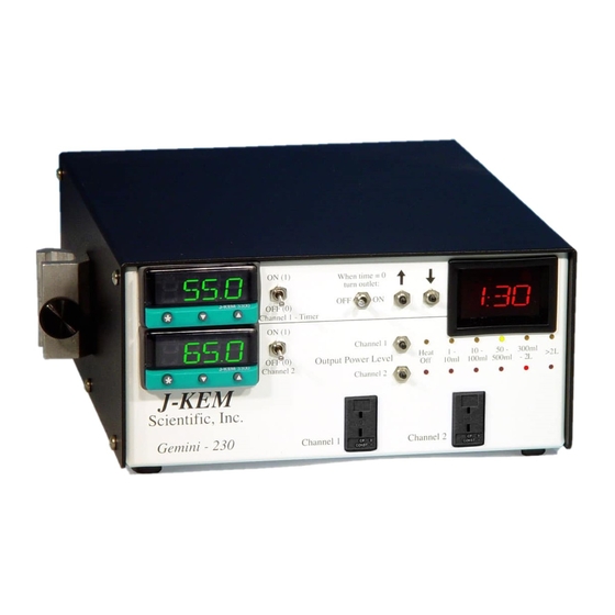
Section 3: Operations Guide Front Panel Description. The Gemini controller has two independent temperature controllers in a single cabinet. The two controllers are labeled Channel 1 and Channel 2. The controls for Channel 1 have no affect on the operation of Channel 2 and visa versa. J-KEM highly recommends that all users read Section 4.4 - How to Set Up a Reaction with J-KEM Scientific’s Digital Temperature Controller prior to using the controller for the first time. - Page 16 have the same color plug as the input (9) on the controller.
-
Page 17: Heater Restrictions
Heater Restrictions. Each channel of the controller can individually deliver up to 10 amps of current at 230 VAC, but the combined total current from Channels 1 & 2 can not exceed 15 amps. These current ratings are limited to resistive loads (heating mantles, hot plates, ovens, etc.). Use only resistive loads that are safely operated at 230 VAC and require less than 10 amps or damage to the controller and a safety hazard may result. - Page 18 controller to stay at the setpoint for the entered time and then turn power to the heater off after the time expires. Important Points to Know While the Ramp-to-Setpoint feature is activated, the display alternates between the current reaction temperature and the word “SPr” to indicate that a “SetPoint Ramp” is active. If this controller is equipped with a digital 100-hour timer, the digital timer and the Ramp-to-Setpoint feature are completely independent of each other.
- Page 19 This plot shows actual data. The green line is the temperature profile when ramping is not used and the reaction heats to the setpoint as normally. The red and blue lines are the result of a ramp run. The red line is the setpoint being ramped at a Ramp runs typically over-shoot the setpoint by a greater amount rate of 2C/min.
-
Page 20: Over Temperature Protection Circuit
NOTE: The controller is shipped with the Over Temperature Protection Circuit DISABLED. To Over Temperature Protection Circuit. activate this circuit for either or both channels, follow Procedure 3 below. Both channels of the Gemini are equipped with over temperature protection circuits. This circuit turns off heating and sounds an audible alarm if the process temperature for Channel 1 and/or Channel 2 exceeds the set point by 5 degrees. -
Page 21: Timer Controls
Timer Controls The 100 hour timer works with Channel 1 only, it has no effect on Channel 2. The timer circuit works in conjunction with the digital meter to determine when power is applied to the heater. The digital meter is the actual temperature controller, the timer circuit only acts as a gatekeeper to determine if the digital meter (temperature controller) is allowed to apply power to the heater or not. - Page 22 Over View of the Timer Functions The timer knob is a multi-function knob. When it’s pushed in for 1/4 second it causes the timer to advance to the next function. When it’s pushed in for 1 second it enters programming mode. In programming mode, the user enters time into the timer or locks the entered time into the timer which starts the program running (a running program can be aborted by holding in the timer knob for 1 second).
- Page 23 Heating for a Set Period of Time In this mode, the user enters the amount of time to heat before turning heating off permanently. This is useful to heat a reaction or other lab instrument for a set period of time and then have the reaction stop heating automatically.
-
Page 24: Output Power Level
Delay Heating for a Set Period of Time In this mode, the user enters an amount of time to delay before turning on power to the heater. This is useful to start heating a reaction or piece of equipment automatically at a specific time. While at this setting and while entering a time into the timer, no power is applied to the heater. - Page 25 Heating Liquids. Each power level is associated with a Front Panel Approx. % of volume range which acts as a guide when heating solutions Volume Range Full Power with heating mantles. When solutions are heated with 1 - 10 mL heating mantles set the power switch to the range that 10 - 100 mL includes the volume of solution being heated [Note: this...
-
Page 26: Temperature Sensor Input
Temperature Sensor Input. Both channels of the controller are fitted with a specific type of thermocouple input and can only be used with a thermocouple of the same type. For the correct temperature to be displayed, the thermocouple type must match the receptacle type on the front of the controller (Figure 1;... -
Page 27: Do's And Don'ts When Using Your Controller
Graph 3 Another factor affecting the choice of power setting is the set point temperature. For set points near room temperature a low power level is adequate. For average temperatures (50 - 100 o ) the volumes printed on the front of the controller are a good guide. -
Page 28: Resetting The Controller For Use With Heating Mantles
3.10 Resetting the Controller for Use With Heating Mantles. If you want to use your controller with heating mantles after it’s been tuned for a different style heater, rather than autotuning the controller with the heating mantle, J-KEM recommends that the controller be manually tuned by following the procedure below. -
Page 29: Changing Between Pid And On/Off Operating Modes
3.12 Changing Between PID and ON/OFF Operating Modes. The controller can heat in either of 2 operating modes, PID (Proportional, Integral, Derivative) or ON/OFF mode. The difference between them is the way they supply power to the heater. In ON/OFF mode (the simplest heating mode), the controller is ON when it’s below the set point and OFF when above. -
Page 30: Troubleshooting
3.13 Troubleshooting. Corrective Problem Cause Action Large over shoot of the set point Output power level is set too high. Set the output power level to a lower setting (see Section 3.6). (Make sure you’ve set the power (> 3 o ) during initial warm-up or level for the channel actually being unstable temperature control. -
Page 31: Fusing
Displayed temperature is The controller has not warmed-up. The display temperature reads low when the controller is first turned incorrect. on, but will self-correct as it warms up. The controller can be used immediately since it will warm up during the initial stages of heating. [Note: Types ‘K’... -
Page 32: Application Notes
Section 4: Application Notes Supplemental application notes on the following topics are available by contacting J-KEM. Application Note Subject How to heat oil baths with your controller. (Included in Appendix) Changing the controllers thermocouple type. Changing the heating outlet into a cooling outlet. Using the controller for unattended fractional distillations. -
Page 33: Controlling A Heating Mantle Temperature Directly
Imagine heating a gallon of water to 80 C in a 5 quart pan on an electric range. Placing the pan on the range and turning the heat to ‘high’ you’d observe a delay in heating while the range coil warmed-up. This delay might be a little annoying, but it's really no problem. - Page 34 Procedure 4 in Section 3.10 will program the controller for heating mantles. For all other heaters, see tuning instructions in Section 2.
-
Page 35: Automatic Storage Of Min/Max Temperatures
After the controller is reprogrammed, place a fine gage wire thermocouple Heating Power Mantle Size Level (≈ 1/3 the size of kite string; available from J-KEM) in the bottom third of 5 & 10 ml 1-10 ml the heating mantle and fit the flask snugly on top so that the thermocouple is 25 ml 10-100 ml in intimate contact with the heating mantle. - Page 36 How to Set Up a Reaction with J-KEM Scientific’s Digital Temperature Controller This application note shows how to set up a typical heated reaction using J-KEM Scientific’s digital temperature controller. For this example, the Model Gemini controller is used, but the application note applies equally well to all J-KEM temperature controller models.
- Page 37 Thermocouples – Thermocouples are color coded. When the plastic connector on the end of the thermocouple is blue, it is a type T thermocouple, when it is yellow it is a type K, and when it is black it is a type J.
- Page 38 Classes of J-KEM Scientific Temperature Controllers J-KEM’s 200-Series, Apollo, and Gemini controllers are compatible with any size heating mantle from 5 ml to 50 liter, and any 120 Vac oil bath (do not use with oil baths rated less than 120 Vac).
- Page 39 Enter the temperature that you want to heat the reaction to (i.e., the Setpoint) into the digital meter. To enter the setpoint temperature (i.e., the temperature to heat to) into the controller: 1. Hold in the Star button on the face of the digital meter.
-
Page 40: Appendix
Appendix Using the Controller With an Oil Bath Application Note #1 Using your 200-Series/Gemini controller with an oil bath is usually not recommended. J-KEM manufactures a 400- Series controller designed for use with oil bath and is recommended for this application. The 200-Series controller can be used safely with oil baths if the instructions in this application note are followed. -
Page 41: Safety Considerations And Accurate Temperature Control
Safety Considerations and Accurate Temperature Control For safety critical and non-typical organic reactions (especially polymeric reactions) or for use with heaters other than heating mantles the user must either 1) monitor the reaction closely to verify the tuning parameters are appropriate for the current application, or 2) autotune the controller for the application. -
Page 42: The Effect Of Power Level And Tuning On Control Stability
III. The Effect of Power Level and Tuning on Control Stability Your J-KEM temperature controller is capable of controlling the temperature of virtually any application with great precision. But, it’s important to know how the controller works and how to adjust it when the controller needs to regulate non-traditional heaters, or heating applications. - Page 43 close. For example, even though every heating mantle size would have a different set of PID settings, your controller is loaded with a single good set of parameters that provides +-0.2 C regulation of all heating mantles sizes from 5 ml to 50 liters. This is possible because, as stated earlier, your controller is quite adaptable to different heating conditions.
- Page 44 Control resulting Standard tuning parameters from autotuning One final plot will help to demonstrate the effects of power and tuning. In the plot above, the same reaction setup is used, but the power applied to the heating mantle increased to the “300 ml – 2 setting (30 watts). This causes the system to heat much faster (the solution hits 240C in about 8 minute rather than 15 minutes when set to the 50 –...
-
Page 45: Resetting The Controller To Original Factory Settings
III. Resetting the Controller to Original Factory Settings J-KEM manufactures the most technically advanced temperature controller available and should give you consistently flawless control. If you have difficulty with your controller, a good place to start to correct the problem is by loading the original factory settings as detailed in the procedure below. If you still have difficulty with your controller, our Engineering Department will help you resolve the problem. - Page 46 Press the ▼ key until the word “LEVL” appears in the display. First hold in the ‘*’ key, then while holding in the ‘*’ key press the ▲ key until “2” appears in the display. Let go of all the keys. Press the ▲...
Need help?
Do you have a question about the Gemini-230 and is the answer not in the manual?
Questions and answers