Table of Contents
Advertisement
Available languages
Available languages
Safe Operation Practices • Set-Up • Operation • Maintenance • Service • Troubleshooting • Warranty
O
'
M
peratOr
s
anual
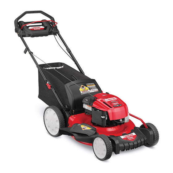
Premium Drive Self Propelled Mower — Models TB360, TB370,
& TB380ES
WARNING
READ AND FOLLOW ALL SAFETY RULES AND INSTRUCTIONS IN THIS MANUAL
BEFORE ATTEMPTING TO OPERATE THIS MACHINE.
FAILURE TO COMPLY WITH THESE INSTRUCTIONS MAY RESULT IN PERSONAL INJURY.
TROY-BILT LLC, P.O. BOX 361131 CLEVELAND, OHIO 44136-0019
Printed In USA
Form No. 769-09271
(November 19, 2013)
Advertisement
Table of Contents

Related Manuals for Troy-Bilt TB360


Summary of Contents for Troy-Bilt TB360
- Page 1 Safe Operation Practices • Set-Up • Operation • Maintenance • Service • Troubleshooting • Warranty ’ peratOr anual Premium Drive Self Propelled Mower — Models TB360, TB370, & TB380ES WARNING READ AND FOLLOW ALL SAFETY RULES AND INSTRUCTIONS IN THIS MANUAL BEFORE ATTEMPTING TO OPERATE THIS MACHINE.
- Page 2 Visit us on the web at www.troybilt.com See How-to Maintenance and Parts Installation Videos at www.troybilt.com/tutorials ◊ Call a Customer Support Representative at (800) 828-5500 or (330) 558-7220 ◊ Write to Troy-Bilt LLC • P.O. Box 361131 • Cleveland, OH • 44136-0019...
- Page 3 Important Safe Operation Practices WARNING: This symbol points out important safety instructions which, if not followed, could endanger the personal safety and/or property of yourself and others. Read and follow all instructions in this manual before attempting to operate this machine. Failure to comply with these instructions may result in personal injury.
- Page 4 A missing or damaged discharge cover can cause blade When starting engine, pull cord slowly until resistance contact or thrown object injuries. is felt, then pull rapidly. Rapid retraction of starter cord (kickback) will pull hand and arm toward engine faster than Many injuries occur as a result of the mower being pulled you can let go.
- Page 5 Service Check the blade and engine mounting bolts at frequent intervals for proper tightness. Also, visually inspect blade Safe Handling Of Gasoline: for damage (e.g., bent, cracked, worn) Replace blade with the original equipment manufacture’s (O.E.M.) blade only, To avoid personal injury or property damage use extreme listed in this manual.
- Page 6 Notice Regarding Emissions Spark Arrestor Engines which are certified to comply with California and federal WARNING: This machine is equipped with an EPA emission regulations for SORE (Small Off Road Equipment) internal combustion engine and should not be used are certified to operate on regular unleaded gasoline, and on or near any unimproved forest-covered, brush may include the following emission control systems: Engine covered or grass-covered land unless the engine’s...
- Page 7 Safety Symbols This page depicts and describes safety symbols that may appear on this product. Read, understand, and follow all instructions on the machine before attempting to assemble and operate. Symbol Description READ THE OPERATOR’S MANUAL(S) Read, understand, and follow all instructions in the manual(s) before attempting to assemble and operate DANGER —...
- Page 8 2 — i ection mportant peration racticeS...
- Page 9 Assembly & Set-Up Contents of Carton • One Lawn Mower • One Grass Catcher • One Bottle of Oil • One Lawn Mower Operator’s Manual • One Engine Operator’s Manual • One Side Discharge Chute • One Fuse† † If Equipped NOTE: Please be aware that this Operator’s Manual covers both the low and high wheel models of this mower. While this section illustrates the high wheel model, the instructions and features are equally applicable to the low wheel model as well, unless otherwise noted. Assembly NOTE: This unit is shipped without gasoline or oil in the engine. Fill up with gasoline and oil as instructed in the accompanying engine manual BEFORE operating your mower. Handle Remove any packing material which may be between upper and lower handles. Remove wing nuts and carriage bolts from handle as shown in Figure 3-1. Do not loosen or remove adjacent hex head screws. Figure 3-2 Remove the T-bolts from the handle brackets as shown in Figure 3-3.
- Page 10 Follow the steps below to complete handle assembly: Pull upward on the handle approximately 8 inches until holes in lower handle (shown in Figure 3-3 deck cutaway) line up with holes in handle bracket. See Figure 3-4. Figure 3-5 The rope guide is attached to the right side of the upper handle.
- Page 11 Grass Catcher To remove grass catcher, lift rear discharge door on the mower. Lift grass catcher up and off of the slots in the handle brackets. Follow steps below to assemble the grass catcher (if Release rear discharge door to allow it to close rear opening of needed).
- Page 12 Adjustments Handle Pitch For convenience of operation, you may adjust the pitch of the Cutting Height handle as follows: The cutting height adjustment lever is located above the rear left Remove wing nuts and carriage bolts from handle. See wheel. Figure 3-12.
- Page 13 Controls and Features Blade Control Premium Drive Control Electric Starter Button† Recoil Starter Cutting Height Adjustment Lever Deck Wash† Side Discharge Chute † If Equipped Figure 4-1 Blade Control Deck Wash (If Equipped) The blade control is attached to the upper handle of the mower. Your mower’s deck is equipped with a water port on its surface Depress and squeeze it against the drive control to operate the as part of its deck wash system.
- Page 14 Operation Starting Engine WARNING: Be sure no one other than the operator is standing near the lawn mower while starting engine or operating mower. Never run engine indoors or in enclosed, poorly ventilated areas. Engine exhaust contains carbon monoxide, an odorless and deadly gas.
- Page 15 Maintenance & Adjustments Maintenance Deck Wash Your mower’s deck may be equipped with a water port on its General Recommendations surface as part of its deck wash system. • Always observe safety rules when performing any Use the deck wash to rinse grass clippings from the deck’s maintenance.
- Page 16 Engine Care Pull the fitting away from the handle. Unhook the cable and remove the metal bushing from the A list of key engine maintenance jobs required for good plastic drive handle. See Figure 6-4. performance by the mower is given below. Follow the accompanying engine manual for a detailed list and instructions.
- Page 17 Service Blade Care Place the blade on the adapter such that the side of the blade marked “Bottom” (or with part number) faces the WARNING: ground when the mower is in the operating position. Make When removing the cutting blade for sharpening or replacement, protect your hands with sure that the blade is aligned and seated on the blade adapter flanges.
- Page 18 Replacing Battery (If Equipped) Charging Battery (If Equipped) WARNING: WARNING: Batteries contain sulfuric acid which The battery contains corrosive fluid may cause burns. Do not short circuit or mutilate and toxic material; handle with care and keep away batteries in any way. Do not put batteries in fire as from children.
- Page 19 Replacing Fuse (If Equipped) Off-Season Storage The electric starter circuit and battery are protected by a 40 The following steps should be taken to prepare your lawn mower ampere fuse. If the fuse burns out, the electric starter will not for storage.
- Page 20 Troubleshooting Problem Cause Remedy Engine Fails to start 1. Blade control disengaged. 1. Engage blade control. 2. Spark plug boot disconnected. 2. Connect wire to spark boot. 3. Fuel tank empty or stale fuel. 3. Fill tank with clean, fresh gasoline. 4.
- Page 21 Problem Cause Remedy Uneven cut 1. Wheels not positioned correctly. 1. Place front and rear wheels in same height position. (Dual Height Adjusters) 2. Dull blade. 2. Sharpen or replace blade. Mower will not self propel 1. Belt not installed properly. 1.
- Page 22 Replacement Parts Component Part Number and Description 759-3336 Spark Plug (Professional Series) BS-591868 Spark Plug (Quantum) BS-795066 Air Filter Element (Professional Series) BS-491588S Air Filter Cartridge (Quantum) BS-493537S Pre-Cleaner (Quantum) BS-799585 Carbon Fuel Tank Cap BS-796577 Fuel Tank Cap BS-298090S Fuel Filter †...
- Page 23 Component Part Number and Description 964-04150B Grass Bag 954-04282 Belt 725-06121 Battery Charger † 725-04903 Battery † 731-09728 Push Key † † If Equipped (800) 828-5500 or (330) 558-7220 Phone to order replacement parts or a complete Parts Manual (have your full model number and serial number ready).
- Page 24 Attachments & Accessories Component Model Number and Description 490-850-0005 Blade Removal Tool — Holds blade in place for faster, safer removal. SPW-134 Spark Plug Wrench — Duel ended wrench to serve multiple uses. Fits ¾” or 13⁄16” hex plug. 490-850-0008 Oil Siphon —...
- Page 25 Component Model Number and Description 22216 STA-BIL® fuel Stabilizer, 32 oz — Treats 80 gallons of fuel. Keeps stored fuel fresh for quick, easy starts. Prevents corrosion from moisture and ethanol-induced attraction. Prevents gum and varnish. 490-290-0012 Mower Cover — Protects your mower against sun, rain and dust damage.
- Page 26 Notes...
- Page 27 11 — n ection oteS...
- Page 28 MANUFACTURER’S LIMITED WARRANTY FOR The limited warranty set forth below is given by Troy-Bilt LLC with Routine maintenance items such as lubricants, filters, blade respect to new merchandise purchased and used in the United States sharpening, tune-ups, brake adjustments, clutch adjustments,...
- Page 29 Medidas importantes de seguridad • Configuración • Funcionamiento • Mantenimiento • Servicio • Solución de problemas • Garantía aNual del operador Podadora tipo abonadora autopropulsada — Modelos TB360, TB370, & TB380ES ADVERTENCIA LEA Y SIGA TODAS LAS INSTRUCCIONES DE ESTE MANUAL ANTES DE PONER EN FUNCIONAMIENTO ESTA MÁQUINA.
- Page 30 Ver Vídeos demostrativos de instalación de mantenimiento y piezas en www.troybilt.com/Tutorials ◊ Llame a un representante de Asistencia al Cliente al (800) 828-5500 ó (330) 558-7220 ◊ Escríbanos a Troy-Bilt LLC • P.O. Box 361131 • Cleveland, OH • 44136-0019...
- Page 31 Medidas importantes de seguridad ADVERTENCIA: La presencia de este símbolo indica que se trata de instrucciones importantes de seguridad que se deben respetar para evitar poner en peligro su seguridad personal y/o material y la de otras personas. Lea y siga todas las instrucciones de este manual antes de poner en funcionamiento esta máquina.
- Page 32 No ponga las manos o los pies cerca de las piezas rotatorias Nunca opere la cortadora sin las guardas apropiadas, o en la tolva de la cortadora. El contacto con las cuchillas cubierta de descarga, guarda para recorte, manija de puede producir la amputación de manos y pies.
- Page 33 Niños Nunca saque la tapa del gas ni agregue combustible mientras el motor está caliente o en marcha. Deje que el Pueden ocurrir accidentes trágicos si el operador no está atento motor se enfríe por lo menos dos minutos antes de volver a a la presencia de niños.
- Page 34 No modifique el motor Nunca trate de ajustar una rueda o la altura de corte mientras el motor está en marcha. Para evitar lesiones graves o la muerte, no modifique el motor Los componentes de la tolva para recorte, cubierta bajo ninguna circunstancia.
- Page 35 Símbolos De Seguridad Esta página representa y describe la seguridad los símbolos que pueden parecer en este producto. Lea, comprenda, y siga todas instrucciones de la máquina antes de intentar ensamblar y operar. Símbolo Descripción LEA EL MANUAL(S) DEL OPERADOR Lea, comprenda, y siga todas instrucciones en el manual (manuales) antes de operar el producto.
- Page 36 2 — M ección edidaS iMportanteS de Seguridad...
- Page 37 Montaje y Configuración Contenido de la caja • Una Podadora • Uno Colector de Césped • Uno Botella del Aceite • Uno Manual de Operador • Uno Manual de Operador de Motor • Uno Canal de Descarga Lateral • Uno Fusible† †Si está...
- Page 38 Siga los siguientes pasos para completar conjunto del La guía de la cuerda está unida al costado derecho de la mango: manija superior. Afloje la tuerca de mariposa que sujeta la guía de la cuerda, Figura 3-6. Tire hacia arriba aproximadamente 8 pulgadas en el asa hasta agujeros en la manija (que se muestra en Figura 3-3 corte de la cubierta) se alinean con los agujeros en el mango soporte.
- Page 39 Canal de Descarga Lateral Su podadora ha sido enviada como abonadora. Si hace la conversión a descarga lateral, asegúrese de que el colector de césped esté fuera de la unidad y que la puerta de descarga trasera esté cerrada. En el costado de la podadora, levante el adaptador para abono.
- Page 40 Ajustes Inclinación de la manija Por conveniencia de la operación, puede ajustar la inclinación de Altura de Corte la manija de la siguiente manera: La palanca de ajuste de altura de corte se ubica por encima de la Quite los tornillos y tuercas de mariposa transporte de rueda izquierda trasera.
- Page 41 Controles Y Características Control de cuchilla Control de la transmisión prima Botón de Arranque Eléctrico† Arrancador de retroceso Palanca de ajuste de altura de corte Lavado de la Plataforma† Canal de Descarga Lateral † De Ser Equipado Figura 4-1 Control de Cuchilla Lavado de la Plataforma (De ser equipado) El control de la cuchilla está...
- Page 42 Funcionamiento Encendido del Motor ADVERTENCIA: Asegúrese que ninguna persona aparte del operador permanezca cerca de la podadora mientras arranca el motor u opera la misma. Nunca encienda un motor en espacios cerrados o en una zona con poca ventilación. El escape del motor contiene monóxido de carbono, un gas inodoro y letal.
- Page 43 Uso como Abonadora ADVERTENCIA: Si golpea un objeto extraño, detenga el motor. Retire el cable de la bujía, Para abonar el césped, quite el colector de césped de la máquina. inspeccione la podadora para ver que no tenga La puerta de descarga posterior deberá estar cerrada. Para daños, y repare el daño antes de reiniciar y operar la un abono eficiente, no corte césped húmedo.
- Page 44 Mantenimiento Y Ajustes Mantenimiento Lavado de la Plataforma La plataforma de su podadora está equipada con un puerto de Recomendaciones Generales agua sobre su superficie como parte del sistema de lavado de la • Respete siempre las reglas de seguridad cuando realice plataforma.
- Page 45 Después de limpiar la plataforma, reinicie la podadora. Mantenga Pase la unión de distancia desde el mango. el motor y la cuchilla en funcionamiento durante dos minutos Desenganchar el cable y retire el casquillo metálico desde por lo menos para permitir que se seque totalmente el lado el asa de la unidad de plástico.
- Page 46 Cuidado de la correa NOTE: Varios componentes deben ser quitados a fin de cambiar el cinturón del cortacésped. Ver a un Distribuidor de Servicio de Troy-Bilt autorizado para hacer sustituir su cinturón. Reemplazo de la batería (De ser equipado) Soporte de...
- Page 47 Carga de la batería (De ser equipado) ADVERTENCIA: La batería contiene fluido corrosivo y material tóxico; manipule con cuidado y mantenga alejado de los niños. No perfore, desensamble, mutile o prenda fuego a la batería. Los gases explosivos podrían purgarse durante la carga o descarga.
- Page 48 Almacenamiento Fuera de Temporada IMPORTANTE: No quite el paquete de baterías del alojamiento del arrancador eléctrico por ninguna razón Se deben seguir estos pasos para la preparación de la podadora que no sea el reemplazo. para su almacenamiento. IMPORTANTE: Siempre conecte el conductor del cargador •...
- Page 49 Notas...
- Page 50 Solución de problemas Problema Causa Remedio El motor no arranca 1. El control de lámina se retiró. 1. Contratar el control de lámina. 2. Alambre de bujía desconectado. 2. Unir el alambre a la bujía. 3. Depósito de combustible combustible vacío 3.
- Page 51 Problema Causa Remedio Demasiada vibración 1. Cuchilla floja o desequilibrada. 1. Apriete la cuchilla y el adaptador. Equilibre la cuchilla. 2. Cuchilla abollada. 2. Consulte a un distribuidor autorizado. La podadora no abona 1. Césped húmedo. 1. No corte el césped cuando está mojado, el césped espere hasta que sea más tarde para hacerlo.
- Page 52 Las disposiciones de esta garantía cubren el recurso de reparación para cuchillas, dientes, bolsas para pasto, ruedas, ruedas para la única y exclusiva que surge de la venta. Troy-Bilt no se hará plataforma de la podadora tractor, asientos, zapatas antideslizantes, responsable de ninguna pérdida o daño incidental o resultante,...
Need help?
Do you have a question about the TB360 and is the answer not in the manual?
Questions and answers
I bought a Troy Built TB360 used from an individual and brought it home kind of anticipating that it may not start right away. I do not know any maintenance history on the mower or if it was primarily only used for a residential yard or used commercially. My guess would be that it was used for residential but again that is only my guess . The mower will crank and turn over and even run but it will not stay running without me spraying starting fluid or carb choke in it. I have checked the spark plug and the fuel line and everything seems to be ok at this point with that. It is a self propel and it does not have a choke or a prime. I believe that it must've been sitting in a garage or something for awhile because the fuel that was in it whenever I bought it was stale and so I had to replace it with the fresh new fuel. I have also taken the Carburetor off and looked at it . It looks clean but it may be something deeper in the internal parts that I cannot see. I have an ultrasonic cleaner and I was wondering if it would be safe to clean the carb in that. I do not know much about small engines or Troy Built but I have a plethora of common sensed so I am sure it can't be that difficult. Also, there is no key to start this mower it was not equipped with one.
What is the proper way to mulch grass with a TB 360? Just close the side and back ports or is there something else! Thanks.