Advertisement
Quick Links
Advertisement

Related Manuals for Asus A55BM-E-BR


Summary of Contents for Asus A55BM-E-BR
- Page 1 A55BM-E/BR...
- Page 2 Product warranty or service will not be extended if: (1) the product is repaired, modified or altered, unless such repair, modification of alteration is authorized in writing by ASUS; or (2) the serial number of the product is defaced or missing.
-
Page 3: Table Of Contents
My Favorites....................2-9 Main menu ....................2-10 Ai Tweaker menu ..................2-11 Advanced menu ..................2-12 Monitor menu ....................2-12 Boot menu ....................2-13 Tools menu ....................2-14 2.10 Exit menu ....................2-14 Appendices Notices ........................A-1 ASUS contact information ..................A-4... -
Page 4: Safety Information
Safety information Electrical safety • To prevent electrical shock hazard, disconnect the power cable from the electrical outlet before relocating the system. • When adding or removing devices to or from the system, ensure that the power cables for the devices are unplugged before the signal cables are connected. If possible, disconnect all power cables from the existing system before you add a device. - Page 5 Refer to the following sources for additional information and for product and software updates. ASUS websites The ASUS website provides updated information on ASUS hardware and software products. Refer to the ASUS contact information. Optional documentation Your product package may include optional documentation, such as warranty flyers, that may have been added by your dealer.
-
Page 6: Package Contents
CPUs. • The maximum 32GB memory capacity can be supported with 16GB or above DIMMs. ASUS will update the memory QVL once the DIMMs are available in the market. • Refer to www.asus.com for the latest Memory QVL (Qualified Vendors List). - Page 7 ASUS unique ASUS 5X Protection features - ASUS motherboards safeguard your PC with 5X Protection: DIGI+VRM, DRAM Fuse, ESD Guards, High-Quality 5K-Hour Solid Capacitors, and Stainless Steel Back I/O to ensure the best quality, reliability, and durability ASUS Digi+ VRM...
- Page 8 1 x 4-pin ATX 12V power connector BIOS 64 Mb Flash ROM, UEFI AMI BIOS, PnP, DMI 2.0, WfM 2.0, SM BIOS 2.6, ACPI 2.0a, Multi-language BIOS, ASUS CrashFree BIOS 3, F12 Printscreen function, F3 Shortcut function, and ASUS DRAM SPD (Serial Presence Detect) memory information...
-
Page 9: Chapter 1: Product Introduction
Before you install or remove any component, ensure that the ATX power supply is switched off or the power cord is detached from the power supply. Failure to do so may cause severe damage to the motherboard, peripherals, or components. ASUS A55BM-E/BR... -
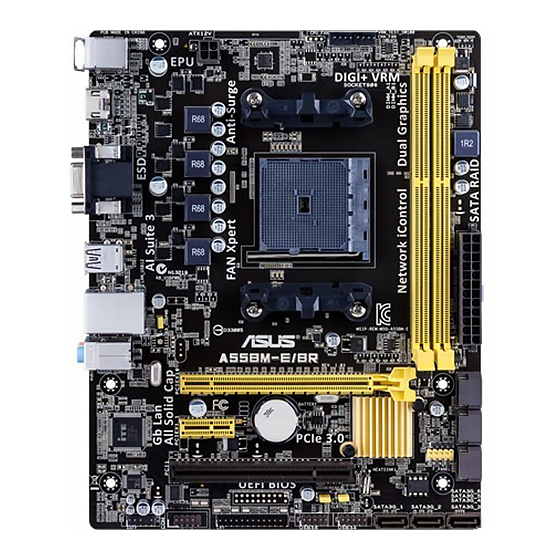
Page 10: Motherboard Overview
Motherboard overview Before you install the motherboard, study the configuration of your chassis to ensure that the motherboard fits into it. Ensure that you unplug the power cord before installing or removing the motherboard. Failure to do so can cause you physical injury and damage motherboard components. 1.2.1 Placement direction When installing the motherboard, ensure that you place it into the chassis in the correct... - Page 11 10. USB 2.0 connectors (10-1 pin USB34, USB56) 11. USB device wake-up (3-pin USBPWF) 12. LPT connector (26-1 pin LPT) 13. Digital audio connector (4-1 pin SPDIF_OUT) 14. Serial port connector (10-1 pin COM) 15. Front panel audio connector (10-1 pin AAFP) ASUS A55BM-E/BR...
-
Page 12: Accelerated Processing Unit (Apu)
Accelerated Processing Unit (APU) This motherboard comes with an FM2+ socket designed for AMD A-series accelerated ® processors with AMD Radeon™ HD 7000/8000 series graphics. ® A55BM-E/BR A55BM-E/BR CPU socket FM2+ Ensure that you use an APU designed for the FM2+ socket. The APU fits in only one correct orientation. - Page 13 1.3.2 APU heatsink and fan assembly installation Apply the Thermal Interface Material to the APU heatsink and APU before you install the heatsink and fan if necessary. To install the APU heatsink and fan assembly ASUS A55BM-E/BR...
- Page 14 To uninstall the APU heatsink and fan assembly Chapter 1: Product introduction...
-
Page 15: System Memory
DDR2 DIMM socket. DDR3 modules are developed for better performance with less power consumption. The figure illustrates the location of the DDR3 DIMM sockets: Channel Sockets Channel A DIMM_A1 Channel B DIMM_B1 A55BM-E/BR A55BM-E/BR 240-pin DDR3 DIMM sockets ASUS A55BM-E/BR... - Page 16 • The maximum 32GB memory capacity can be supported with 16GB or above DIMMs. ASUS will update the memory QVL once the DIMMs are available in the market. • The default memory operation frequency is dependent on its Serial Presence Detect (SPD), which is the standard way of accessing information from a memory module.
- Page 17 1.4.3 Installing a DIMM To remove a DIMM ASUS A55BM-E/BR...
-
Page 18: Expansion Slots
Expansion slots In the future, you may need to install expansion cards. The following sub-sections describe the slots and the expansion cards that they support. Unplug the power cord before adding or removing expansion cards. Failure to do so may cause you physical injury and damage motherboard components. -
Page 19: Jumpers
CMOS memory of date, time, and system setup parameters by erasing the CMOS RTC RAM data. The onboard button cell battery powers the RAM data in CMOS, which include system setup information such as system passwords. CLRTC A55BM-E/BR Normal Clear RTC (Default) A55BM-E/BR Clear RTC RAM ASUS A55BM-E/BR 1-11... - Page 20 To erase the RTC RAM: Turn OFF the computer and unplug the power cord. Move the jumper cap from pins 1-2 (default) to pins 2-3. Keep the cap on pins 2-3 for about 5-10 seconds, then move the cap back to pins 1-2. Plug the power cord and turn ON the computer.
-
Page 21: Connectors
HDCP compliant allowing playback of HD DVD, Blu-ray, and other protected content. Video Graphics Adapter (VGA) port. This 15-pin port is for a VGA monitor or other VGA-compatible devices. LAN (RJ-45) port. This port allows Gigabit connection to a Local Area Network (LAN) through a network hub. ASUS A55BM-E/BR 1-13... - Page 22 LAN port LED indications ACT/LINK SPEED Activity/Link LED Speed LED Status Description Status Description No link 10Mbps connection Orange Linked ORANGE 100Mbps connection LAN port Orange (Blinking) Data activity GREEN 1Gbps connection Orange (Blinking Ready to wake up then steady) from S5 mode Line In port (light blue).
- Page 23 These are not jumpers! DO NOT place jumper caps on the fan connectors. • The CPU_FAN connector supports a CPU fan of maximum 2A (24 W) fan power. • The CPU_FAN and CHA_FAN connectors support the ASUS Fan Xpert feature. ASUS A55BM-E/BR 1-15...
- Page 24 The system may become unstable or may not boot up if the power is inadequate. • If you are uncertain about the minimum power supply requirement for your system, refer to the Recommended Power Supply Wattage Calculator at http://support.asus. com/PowerSupplyCalculator/PSCalculator.aspx?SLanguage=en-us for details. 1-16 Chapter 1: Product introduction...
- Page 25 ATA hard disk drives. The Serial ATA RAID feature is available only if you are using Windows XP SP3 or later version. ® • When using hot-plug and NCQ, set the type of the SATA connectors in the BIOS to [AHCI]. ASUS A55BM-E/BR 1-17...
- Page 26 System panel connector (10-1 pin PANEL) This connector supports several chassis-mounted functions. F_PANEL +PWR LED PWR BTN PIN 1 A55BM-E/BR +HDD_LED RESET A55BM-E/BR System panel connector • System power LED (2-pin PWR_LED) This 2-pin connector is for the system power LED. Connect the chassis power LED cable to this connector.
- Page 27 • If you want to connect a high definition front panel audio module to this connector, set the Front Panel Type item in the BIOS to [HD]. • The front panel audio I/O module is purchased separately. ASUS A55BM-E/BR 1-19...
- Page 28 USB 2.0 connectors (10-1 pin USB34, USB56) These connectors are for USB 2.0 ports. Connect the USB module cable to any of these connectors, then install the module to a slot opening at the back of the system chassis. These USB connectors comply with USB 2.0 specification that supports up to 480Mbps connection speed.
-
Page 29: Software Support
The Support DVD that comes with the motherboard package contains the drivers, software applications, and utilities that you can install to avail all motherboard features. The contents of the Support DVD are subject to change at any time without notice. Visit the ASUS website at www.asus.com for updates. ASUS A55BM-E/BR 1-21... - Page 30 Place the Support DVD into the optical drive. If Autorun is enabled in your computer, the DVD automatically displays the Specials screen which contains the unique features of ASUS motherboard. Click Drivers, Utilities, Make Disk, Manual, Contact and Specials tabs to display their respective menus.
Need help?
Do you have a question about the A55BM-E-BR and is the answer not in the manual?
Questions and answers