Panasonic WV-SC385PJ Installation Manual
Hide thumbs
Also See for WV-SC385PJ:
- Operating instructions manual (244 pages) ,
- Operating instructions manual (244 pages)
Table of Contents
Advertisement
Quick Links
Installation Guide
Network Camera
WV-SC385PJ
Model No.
WV-SC385, WV-SC384
WV-SC385E, WV-SC384E
L O C K
O P E N
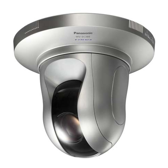
(This illustration represents WV-SC385.)
Before attempting to connect or operate this product,
please read these instructions carefully and save this manual for future use.
The model number is abbreviated in some descriptions in this manual.
Advertisement
Table of Contents

Related Manuals for Panasonic WV-SC385PJ


Summary of Contents for Panasonic WV-SC385PJ
- Page 1 Installation Guide Network Camera WV-SC385PJ Model No. WV-SC385, WV-SC384 WV-SC385E, WV-SC384E L O C K O P E N (This illustration represents WV-SC385.) Before attempting to connect or operate this product, please read these instructions carefully and save this manual for future use.
- Page 2 • The apparatus should not be exposed to dripping or For U.S. and Canada: splashing and that no objects filled with liquids, such as WV-SC385, WV-SC385PJ, WV-SC384 vases, should be placed on the apparatus. For Europe and other countries: • All work related to the installation of this product should be WV-SC385E, WV-SC384E made by qualified service personnel or system installers.
-
Page 3: Table Of Contents
Contents Important safety instructions ............................. 4 Limitation of liability ................................5 Disclaimer of warranty ............................... 5 Preface ....................................6 Main functions ................................... 6 About the user manuals ..............................7 About notations ................................. 7 System requirements for a PC ............................7 Trademarks and registered trademarks.......................... -
Page 4: Important Safety Instructions
Important safety instructions 1) Read these instructions. 2) Keep these instructions. 3) Heed all warnings. 4) Follow all instructions. 5) Do not use this apparatus near water. 6) Clean only with dry cloth. 7) Do not block any ventilation openings. Install in accordance with the manufacturer's instructions. 8) Do not install near any heat sources such as radiators, heat registers, stoves, or other apparatus (including amplifiers) that produce heat. -
Page 5: Limitation Of Liability
THE CORRESPONDING PRODUCT (S). Disclaimer of warranty IN NO EVENT SHALL Panasonic System Networks Co., Ltd. BE LIABLE TO ANY PARTY OR ANY PERSON, EXCEPT FOR REPLACEMENT OR REASONABLE MAINTENANCE OF THE PRODUCT, FOR THE CASES, INCLUDING BUT NOT LIMITED TO BELOW: (1) ANY DAMAGE AND LOSS, INCLUDING WITHOUT LIMITATION, DIRECT OR INDIRECT, SPECIAL, CONSEQUENTIAL OR EXEMPLARY, ARISING OUT OF OR RELATING TO THE PRODUCT;... -
Page 6: Preface
Preface The network cameras WV-SC385/WV-SC384 are designed to operate using a PC on a network (10BASE-T/100BASE-TX). By connecting to a network (LAN) or the Internet, images and audio from the camera can be monitored on a PC via a net- work. -
Page 7: About The User Manuals
About the user manuals There are 2 sets of operating instructions for the WV-SC385, WV-SC385PJ, WV-SC384 (NTSC model), WV-SC385E, WV-SC384E (PAL model) as follows. • Installation Guide: Explains how to install and connect devices, as well as how to connect and configure the network. • Operating Instructions (PDF): Explains how to perform the settings and how to operate this camera. The Operating Instructions covers the models: WV-SW395, WV-SC385, WV-SC385PJ, WV-SC384, WV-SW395E, WV-SC385E, WV-SC384E. -
Page 8: Trademarks And Registered Trademarks
Important: • When using a PC that does not meet the above requirements, displaying of images may become slower or the web browser may become inoperable. • Audio may not be heard if a sound card is not installed on a PC. Audio may be interrupted depending on the network environment. • Microsoft ® Windows ® XP Professional 64-bit Edition is not supported. • When using IPv6 for communication, use Microsoft ® Windows ® 7 or Microsoft ® Windows Vista ® Note: • Refer to "Notes on Windows Vista ® / Windows ®... -
Page 9: Precautions
Precautions Refer installation work to the dealer. The exclusively designed mount bracket shall be Installation work requires technique and experiences. used. Failure to observe this may cause a drop resulting in injury Failure to observe this may cause fire, electric shock, injury, or damage to the product. - Page 10 [Precautions for use] About SDHC/SD memory card • Before inserting the SDHC/SD memory card, turn off This product is designed to be used indoors. This the power of this product first. Otherwise, it may product is not operable outdoors. cause malfunction or damage data recorded on the SDHC/SD memory card.
- Page 11 AVC Patent Portfolio License THIS PRODUCT IS LICENSED UNDER THE AVC PATENT PORTFOLIO LICENSE FOR THE PERSONAL USE OF A CONSUMER OR OTHER USES IN WHICH IT DOES NOT RECEIVE REMUNERATION TO (i) ENCODE VIDEO IN COMPLIANCE WITH THE AVC STANDARD ("AVC VIDEO") AND/OR (ii) DECODE AVC VIDEO THAT WAS ENCODED BY A CONSUMER ENGAGED IN A PERSONAL ACTIVITY AND/OR WAS OBTAINED FROM A...
-
Page 12: Precautions For Installation
Precautions for installation Panasonic assumes no responsibility for injuries or property damage resulting from failures arising out of improper installation or operation inconsistent with this documentation. Installing place Screw tightening • The screws and bolts must be tightened with an Contact your dealer for assistance if you are unsure of an appropriate place in your particular environment. -
Page 13: Major Operating Controls
(fixed with the mount bracket) LO CK O P E N Decorative cover (accessory) Live indicator Camera (This illustration represents WV-SC385.) Front view Transparent part (over the lens) WV-SC385 WV-SC385 SDHC/SD memory card slot cover SDHC/SD memory card slot Panasonic logo plate... - Page 14 Rear view INITIAL SET button Cable guide Access indicator (blinking at accessing) Audio output connector 10BASE-T/ Link indicator 100BASE-TX LINK INITIAL POWER EXT I/O MIC/LINE IN AUDIO OUT MONITOR OUT Monitor out connector (lighting at linking) for adjustment 12V IN 4 3 2 1 Network connector Safety wire holder...
-
Page 15: Installations/Connections
Installations/Connections Caution: • FOR UL LISTED MODEL(S), ONLY CONNECT 12 V DC CLASS 2 POWER SUPPLY. This camera is designed to be installed on a ceiling. Before starting the installation/connection, prepare the required devices and cables. Before starting the connection, turn off the power of the devices including the camera and the PC or disconnect from the 12 V DC power supply. - Page 16 Wire through a hole in the ceiling Step 1 Step 3 Fix the camera mount bracket (accessory) with four Insert the SDHC/SD memory card into the SDHC/SD optional fixing screws (M4 or M6, option). memory card slot. Refer to page 26 for how to insert the There should be no obstacles such as wall in a range of SDHC/SD memory card.
- Page 17 Specification of cable (wire): AWG #22 - #28, Single core, twisted Important: Strip range • Connect/disconnect the audio cables and turn on the power of the camera after turning off the power of the Approx. 9 mm - 10 mm audio output devices. Otherwise, loud noise may be {11/32 inches - 13/32 inches} EXT I/O terminal 2 heard from the speaker.
- Page 18 Center of the Step 8 camera mount bracket Connect the cables to the network connector and the power inlet. Important: • When the power of the camera is turned on, the cam- era will start panning and the position will automati- Base part Guide part cally be initialized. Lock plate • Do not touch the camera in the process of initializa- tion.
- Page 19 • 12 V DC power supply terminal Step 9 q Loosen the screw of the power cable plug (accesso- After completing the cable connections, attach the deco- ry). rative cover (accessory). w Connect the output cable to the power cable plug. Strip 3 mm to 7 mm {1/8 inches to 9/32 inches} from q Align the indication "OPEN"...
- Page 20 Wire without making a hole in the ceiling Step 1 Install the camera by following step 1 and steps 3 - 8 of the "Wire through a hole in the ceiling" section (☞ pages 16 - 18). It is unnecessary to make a hole in the ceiling as described in step O P E 2 of the "Wire through a hole in the ceiling"...
- Page 21 Place the camera upside-down on a desktop without fixing SC385 Use it as a simple desktop device at meetings and on other occasions. Place the camera on a level place not subject to vibrations. Ensure that the camera does not fall. When using the camera upside-down, select "On (desktop)"...
- Page 22 Installation examples The following are installation examples in which a mount bracket (option) is used with this camera. <For using the WV-Q154S> • Embedded box (locally procured) • Strong wall Embedded box (locally procured) WV-Q154S (option) Camera • Concrete Anchor bolt Anchor bolt (locally procured) (locally procured)
- Page 23 <For using the WV-Q156S> WV-Q105 (option) Anchor bolt Mounting screws (4 pcs, WV-Q105 supplied) Safety wire angle Ceiling board such as plaster board Safety wire WV-Q156S (option) Inner cover Camera Dome cover...
- Page 24 Connection example When connecting with a PC directly Powered speaker (option) LAN cable Microphone (option) (category 5 or better, cross, STP*) To AC outlet <Required cable> LAN cable (category 5 or better, cross, STP*) * PAL model only When connecting to a network using a PoE hub Video monitor (for adjustment use only) Powered speaker...
-
Page 25: Detach The Camera
Detach the camera The camera is fixed on the camera mount bracket using the fixing screw. Remove the camera by following the instructions below. Important: • Do not detach the camera in a different way from the one described below. It may damage the camera. Step 1 Rotate the decorative cover (accessory) counterclockwise until the indication "OPEN" reached the decorative cover guide of the camera mount bracket (accessory). -
Page 26: Insert/Remove An Sdhc/Sd Memory Card
Step 1 Step 4 Push the left corner of the Panasonic logo plate on the Shut the SDHC/SD memory card slot cover and lock the front panel to unlock the SDHC/SD memory card slot cover by pushing the Panasonic logo plate. - Page 27 Step 2 Push the SDHC/SD memory card until a click is heard and then pull the SDHC/SD memory card from the slot. Step 3 Shut the SDHC/SD memory card slot cover and lock the cover by pushing the Panasonic logo plate.
-
Page 28: Configure The Network Settings
When using multiple cameras, it is necessary to configure the network settings of each camera independently. If the Panasonic IP setting software does not work, configure the network settings of the camera and the PC individually on the "Network" page of the setup menu. Refer to the Operating Instructions (PDF) for further information. - Page 29 Step 1 Step 3 Start the Panasonic IP setting software by double-clicking Complete each network setup item and click the [Save] the "EasyIpSetup.exe" icon on the provided CD-ROM. button. The License Agreement will be displayed. Read the Agreement and choose "I accept the term in the license agreement", and click "OK".
-
Page 30: Troubleshooting
Troubleshooting Before asking for repairs, check the symptoms with the following table. Contact your dealer if a problem cannot be solved even after checking and trying the solution in the table or a problem is not described below. Reference Symptom Cause/solution pages When using DC power supply... - Page 31 Live indicator lights red. Instructions Or install the software to format the SDHC/SD memory card on (PDF) the PC. Refer to our website (http://panasonic.net/pss/security/ support/info.html) for further information about the supported soft- ware. • Isn't the inserted SDHC/SD memory card faulty? Replace the card with a normal one.
- Page 32 The addresses (local addresses) of the same class must be set for the PC and the camera to be used in the same network. Change the IP address by using the "Panasonic IP setting" software. Then, access the camera again.
- Page 33 About the live indicator The live indicator will light or blink as follows depending on the camera status. Operation status Indicator status When the power is turned on Before the network Blinks orange connection is established When the network Blinks orange → Blinks green → Lights green connection is established During the standby or connection (Cable is not connected.) Lights orange...
-
Page 34: Specifications
Specifications • Basic Power source: 12 V DC, PoE (IEEE802.3af compliant) Power consumption: WV-SC385: 12 V DC*: 1 A, PoE 48 V: 12 W/230 mA (Class 0 device) WV-SC384: 12 V DC*: 690 mA, PoE 48 V: 10 W/190 mA (Class 0 device) * FOR UL LISTED MODEL(S), ONLY CONNECT 12 V DC CLASS 2 POWER SUPPLY. - Page 35 Auto slow shutter: Off (1/30 s), max. 2/30 s, max. 4/30 s, max. 6/30 s, max. 10/30 s, max. 16/30 s Color/BW (SC385): On/ Off/ AUTO1/ AUTO2/ AUTO3 Simple black & white mode (SC384): Off/Auto White balance: ATW1/ ATW2/ AWC Digital noise reduction: High/Low Image stabilizer:...
- Page 36 (Including the camera itself) Compatible SDHC/ SD memory card (option): Manufactured by Panasonic SDHC memory card: 4 GB, 8 GB, 16 GB, 32 GB SD memory card: 256 MB, 512 MB, 1 GB, 2 GB (except miniSD card and microSD card)
-
Page 37: Standard Accessories
Standard accessories Installation Guide (this document) ........1 pc. Warranty card (NTSC model only) ........1 pc. CD-ROM* ...............1 pc. Code label* ..............1 pc. *1 The CD-ROM contains the operating instructions (PDFs) and different kinds of tool software programs. *2 This label may be required for network management. The network administrator shall retain the code label. The following parts are used during installation procedures. - Page 38 Information for Users on Collection and Disposal of Old Equipment and used Batteries These symbols on the products, packaging, and/or accompanying documents mean that used electrical and electronic products and batteries should not be mixed with general household waste. For proper treatment, recovery and recycling of old products and used batteries, please take them to applicable collection points, in accordance with your national legislation and the Directives 2002/96/EC and 2006/66/EC.
- Page 40 Unit of Panasonic Corporation of North America www.panasonic.com/business/ Importer's name and address to follow EU rules: For customer support, call 1.800.528.6747 Three Panasonic Way, Secaucus, New Jersey 07094 U.S.A. Panasonic Testing Centre Panasonic Marketing Europe GmbH Panasonic Canada Inc. Winsbergring 15, 22525 Hamburg F.R.Germany...
Need help?
Do you have a question about the WV-SC385PJ and is the answer not in the manual?
Questions and answers