Table of Contents
Advertisement
Quick Links
Repair
™
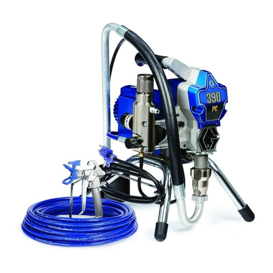
390
Electric Airless Sprayer
- For portable spray application of architectural paints and coatings -
Models: 253958, 262019, 254968, 254969, 254998, 253961, 262024, 256392, 256481, 826024
Maximum Working Pressure: 3300 psi (227 bar, 22.7 MPa)
Important Safety Instructions
Read all warnings and instructions in this manual. Save these instructions.
US Patent No.: D580,515 S and D580,518 S
Taiwan Patent No.: D129255
Korean Patent No.: 30-548399
Stand
ProStep
ti5635b
ti11583a
Related Manuals
310820, 311732
311861
309250
311761
ti11626a
Hi-Boy
311737G
EN
Advertisement
Table of Contents

Summary of Contents for Graco 311737G
- Page 1 Repair ™ 311737G Electric Airless Sprayer - For portable spray application of architectural paints and coatings - Models: 253958, 262019, 254968, 254969, 254998, 253961, 262024, 256392, 256481, 826024 Maximum Working Pressure: 3300 psi (227 bar, 22.7 MPa) Important Safety Instructions Read all warnings and instructions in this manual.
- Page 2 Models Models Model Country ✓ 254968, 254969, 256391 230 CCE Europe / Europe Multicord ✓ 253961, 256481 110 UK ✓ 254998 230 Asia Australia ✓ 262019, 253958,826084 North America ✓ 254998, 262024, 256392 Asia 311737G...
- Page 3 Make sure your extension cord is not damaged. If an extension cord is necessary, use 12 AWG (2.5 mm ) minimum to carry the current that the product draws. • An undersized cord results in a drop in line voltage and loss of power and overheating. 311737G...
- Page 4 Do not stop or deflect leaks with your hand, body, glove, or rag. • Engage trigger lock when not spraying. • Follow Pressure Relief Procedure in this manual, when you stop spraying and before cleaning, checking, or servicing equipment. 311737G...
- Page 5 Do not kink or over-bend the hose. • Do not expose the hose to temperatures or to pressures in excess of those specified by Graco. • Do not use the hose as a strength member to pull or lift the equipment.
-
Page 6: Component Identification
Component Identification Component Identification ti12008a Item Component Pressure Control ON/OFF switch Power Cord Fluid Outlet Prime Valve Pump Suction Hose Drain Hose Fluid Hose Guard Trigger Safety Lock Model/Serial Tag Filter Platform Pressure Control 311737G... -
Page 7: Installation
To maintain grounding continuity when flushing or relieving pressure: hold metal part of the spray gun firmly to the side of a grounded metal pail, then trigger the gun. 311737G... -
Page 8: Pressure Relief Procedure
VERY SLOWLY loosen tip guard retaining nut or hose end coupling to relieve pressure gradually, then loosen completely. Clear hose or tip obstruction. 4. Engage trigger safety lock on gun if unit is being shut down or left unattended. ti8324 c ti5310c 311737G... -
Page 9: General Repair Information
Pump Armor to protect sprayer during storage. • Do not operate the sprayer without the motor shroud in place. Replace if damaged. Motor shroud directs cooling air around motor to prevent overheating and insulate the control board from accidental electric shock. 311737G... -
Page 10: Troubleshooting
3. Motor. Remove drive housing Replace motor if fan won’t turn. See page 28, assembly. See page 16, Drive Motor Replacement. Housing Replacement. Try to rotate fan by hand. 311737G... - Page 11 10. Motor armature for shorts using Replace motor. See page 28, Motor Replace- armature tester (growler) or per- ment. form spin test, page 17. 11. Pressure control not plugged in Insert pressure control connector into control to control board. board. 311737G...
- Page 12 Replace pressure control assembly. See page control knob fully clockwise. 23, Pressure Control Assembly Replace- ment. 12. Motor armature for shorts by Replace motor. See page 28, Motor using an armature tester Replacement. (growler) or perform spin test, page 17. 311737G...
- Page 13 3. Tightness of pump packing nut. Loosen packing nut. Check for leaking around Overtightening tightens packings throat. Replace pump packings if necessary. on rod, restricts pump action and See pump manual 309250. damages packings. 311737G...
- Page 14 2. Loosen two screws (30) and rotate cover (44). 3. Loosen nut (A) and remove suction hose (35). Loosen nut (B) and remove the high pressure hose 7. Using a hammer, loosen pump jam nut (11). (14). Unscrew and remove pump (9). ti6107b ti6105b 311737G...
- Page 15 3. Install pump pin (32). Verify retainer spring (C) is in groove over pump pin. ti6108b ti6105b 9. Fill packing nut with Graco TSL until fluid flows onto top of seal. Rotate cover (44). Tighten screws (30). 4. Push pump (9) up until pump threads engage. ti5735b...
- Page 16 4. Install cover (32) with two screws (30). NOTICE Do not drop gear cluster (3) and (2) when removing 5. Install pump (9). Displacement Pump Replace- drive housing (5). Gear cluster may stay engaged in ment, page 14. motor front endbell or drive housing. 311737G...
- Page 17 4. Reattach motor connector (F). 1. Connect red and black motor leads with test lead. 5. Replace drive housing, page 16. Turn motor fan by hand at about two revolutions per second. 6. Replace shroud (29) and two screws (30). 311737G...
-
Page 18: Fan Replacement
2. Install spring clip (1b). 2. Remove two screws (30) and shroud (29). 3. Replace shroud (29) and two screws (30). 3. Remove spring clip (1b) on back of motor. ti5769b 311737G... -
Page 19: Motor Brush Replacement
(black) brush lead in the side of the ti5637a motor. 8. Replace shroud (29) and two screws (30) (see illus- 2. Push each cap (A) into place over brush. Orient tration, page 17). each cap with the 2 projections on either side of the 311737G... -
Page 20: Control Board Replacement
4. Disconnect motor connector (B) from control board (33). 5. Remove 3 screws (30) securing control board to housing (2 are located on the front and one on the 240V back next to the power cord). 120V ti6143a ti6119b 311737G... - Page 21 5. Reattach motor connector (B) and pressure control high pressure hose to the manifold and the sprayer assembly connector (A). frame. 6. Install shroud (29) and two screws (30) (see illustra- tion, page 17). Hose Power Cord ti8322a Bottom View of Sprayer 311737G...
-
Page 22: Fuse Replacement
Removal 2. Install shroud (29) and two screws (30) (see illustra- 1. Relieve pressure, page 8. Disconnect power cord tion, page 17). from outlet. 2. Remove two screws (30) and shroud (29) (see illus- tration, page 17). Replaceable Fuse 311737G... - Page 23 7. Install shroud (29) and two screws (30) (see illustra- and torque to 150 in-lbs (17.0 N.m) tion, page 15). NOTE: Be careful when tightening pressure control knob that wires do not get pinched between the pres- sure control assembly and fluid manifold. 311737G...
-
Page 24: Manifold Replacement
23. 4. Feed pressure switch wires through hole in housing (K). 5. Insert grommet (21) in hole (K) in housing. Secure wires to manifold housing with tape (22). ti12077a 6. Reconnect pressure switch connector (A) to control board (33). 311737G... - Page 25 4. Replace pin (26) in drain handle (25). If necessary, 3. Pull drain handle (25) and base (24) off drain valve use a hammer to tap it in place completely. (23). 4. Using a wrench, loosen drain valve (23) and remove it from manifold (15). ti8384a 311737G...
- Page 26 NOTE: If you are only replacing the manifold and will be reusing the existing barbed fitting (20) and drain line (40), you will need to use a sharp knife to cut the remaining drain line material off the end of the barbed fitting (20). ti8333a 311737G...
-
Page 27: Power Cord Replacement
2. Disconnect power cord connectors (C and D) from switch connect (A). control board (33). 5. Install shroud (29) and two screws (30) (see illustra- 3. Disconnect green ground wire (G) from sprayer by tion, page 17). loosening grounding screw (31). 120V 240V 311737G... -
Page 28: Motor Replacement
4. Remove Pressure (Fluid) Manifold, Manifold ment, page 14. Replacement, page 24. 7. Install shroud (29) with two screws (30) (see illustra- 5. Disconnect all leads from board (33) and remove tion, page 17). control board. Control Board Replacement, page Liberally apply grease ti5642b 311737G... -
Page 29: Wiring Diagram
Pressure Control Assembly ON/OFF Switch ti5643a Black Capacitor Power White Plug Green ti5643a Pressure Control 240V Model Assembly from Motor Red (+) 2 x Yellow Capacitor Black (-) Replaceable Fuse ON/OFF Switch ti5857a Blue Brown Power Plug Green ti5857a 311737G... -
Page 30: Technical Data
Wetted parts ........zinc and nickel-plated carbon steel, nylon, stainless steel, PTFE, Acetal, leather, UHMWPE, aluminum, tungsten carbide Noise level* Sound power (IS0 3744) 100dBa* Sound pressure (ISO 3744) 90 dBa* *Measured 3 feet (1 meter) from equipment. 311737G... - Page 31 Notes Notes 311737G...
-
Page 32: Graco Standard Warranty
With the exception of any special, extended, or limited warranty published by Graco, Graco will, for a period of twelve months from the date of sale, repair or replace any part of the equipment determined by Graco to be defective.