Table of Contents
Advertisement
Quick Links
Advertisement
Table of Contents

Subscribe to Our Youtube Channel
Related Manuals for Tannoy Arena Highline 300

Summary of Contents for Tannoy Arena Highline 300
- Page 1 O W N E R ’S M A N U A L...
-
Page 2: Table Of Contents
CONNECT TO RECEIVER SPECIFICATIONS WARRANTY This equipment has been produced and tested with care and precision. All Tannoy speaker systems are built to give first class service and carry a 5-year warranty. Active subwoofers carry a 1-year warranty. If the equipment proves to be defective within this period for any reason other than accident, misuse, unauthorised modification or fair wear and tear, Tannoy will repair any such defect or, at our option, replace it without charge for parts, labour or return carriage. -
Page 3: Introduction
INTRODUCTION Thank you for selecting Tannoy loudspeakers developed in the UK by our dedicated team of design engineers. The Tannoy Arena Highline 300™ speakers are designed to blend perfectly into your room and provide a sound stage which is at least as good as you would hear in a commercial movie theatre, but in the comfort of your own home. -
Page 4: Satellite What's In The Box
SATELLITE What’s in the box? 1 x Satellite speaker 1 x Long wall bracket 1 x Short bracket with pre-fitted cap 1 x Short bracket without pre-fitted cap 1 x Bracket cap 4 x 8mm Silver hex socket fixing screw + lock washers 1 x 5mm black cap head fixing screw + spring washer 1 x Ball nosed Allen key Required but not included:... -
Page 5: How To Wall Mount
SATELLITE How to wall mount WARNING: It is your responsibility to ensure that the bracket to wall fixing screws or bolts and the walls themselves are strong enough to support the weight of the speaker – refer to the speaker weight specifications supplied in this manual. - Page 6 SATELLITE How to wall mount - continued Cut the speaker wire so that the (+) side is slightly longer than the (-) side and feed the speaker wire through spare bracket cap. Important Note: It is essential that the speakers are wired correctly at this stage. The (-) wire should have a solid black line, or similar, marked along it.
- Page 7 SATELLITE How to wall mount - continued Fix spare cap to bottom of bracket using cap screw and spring washer provided...
-
Page 8: Stand Mount What's In The Box
STAND MOUNT What’s in the box? 1 x Stand mount 2 x Lock washers 2 x Fixing screws 6 x Spikes 6 x Rubber feet 6 x M6 nuts... -
Page 9: How To Stand Mount
STAND MOUNT How to stand mount Attach the spike kits, or rubber feet, to the bottom of the stand then thread the cable through the stand base and shaft. Cut the speaker wire so that the (+) wire is slightly longer than the (-) wire. Screw the (+) wire into the red terminal and screw (-) wire into black terminal. -
Page 10: Centre Channel What's In The Box
CENTRE CHANNEL What’s in the box? 1 x Centre speaker 1 x Long wall bracket 1 x Short bracket with pre-fitted cap 1 x Short bracket without pre-fitted cap 1 x Bracket cap 4 x 8mm Silver hex socket fixing screw + lock washers 1 x 5mm Black cap head fixing screw + spring washer 1 x Ball nosed allen key 1 x Small stand... -
Page 11: How To Wall Mount
CENTRE CHANNEL How to wall mount WARNING: It is your responsibility to ensure that the bracket to wall fixing screws or bolts and the walls themselves are strong enough to support the weight of the speaker - refer to the speaker weight specifications supplied in this manual. Particular care is needed when fixing to hollow or cavity walls - ‘'stud’' walls. - Page 12 CENTRE CHANNEL How to wall mount - continued Offer the speaker up to the wall bracket half way along. Engage speaker with bracket and slide across. Ensure cap is fully engaged with the wall bracket. Fix spare cap to bottom of bracket using the cap screw and spring washer provided.
-
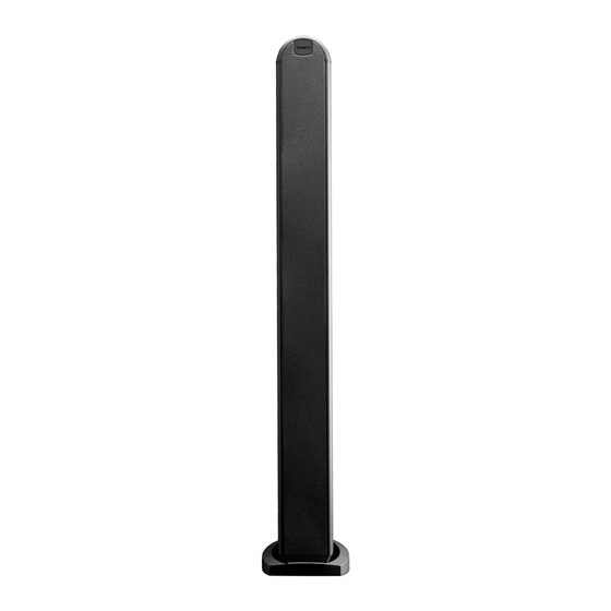
Page 13: Tower
TOWER What’s in the box? 1 x Tower speaker 6 x Spikes 6 x Rubber Feet 6 x M6 Nuts Required but not included: Sufficient cable for your requirements... -
Page 14: How To Connect
TOWER How to connect Attach the spike kits or rubber feet to the base of the tower then thread the speaker cable through the base. Cut the speaker wire so that the (+) wire is slightly longer than the (-). Screw the (+) wire into the red terminal and screw (-) wire into the black terminal. -
Page 15: Room Setup
ROOM SETUP A 5.1 surround sound system consists of 5 separate speakers and 1 subwoofer. The centre channel is designed to reproduce most of the dialogue or solo performances. The front left and right speakers reproduce the left/right stereo information and special effects. -
Page 16: Connect To Receiver
CONNECTING THE SYSTEM TO YOUR AV RECEIVER Wire up the system connecting each speaker to the appropriate terminals on the receiver or amplifier making sure that cables connect red to red terminals (+ to +) and black to black terminals (- to - ). Please note : (+) is shown as grey, (-) is shown as white. -
Page 17: Specifications
TECHNICAL SPECIFICATIONS ARENA HIGHLINE 300, CENTRE & SATELLITE SPEAKER PERFORMANCE: Recommended amplifier power 25 - 75W RMS Maximum sensitivity (2.83V @ 1m) 87dB Nominal impedance 8 Ohm Frequency response (-6dB) 95Hz - 62kHz Drivers 4 x 75mm (3”) LF/MF with 19mm (0.75”) HF Crossover frequency 300Hz, 6.0kHz... - Page 18 TECHNICAL SPECIFICATIONS ARENA HIGHLINE 300 SATELLITE ACCESSORY STAND Weight 5.9kg (13lbs) Dimensions H x W x D 759.50 x 173.0 x 175.0 mm (29.90 x 6.81 x 6.89 ins) Finish Black gloss or silver gloss 998.0mm (39.29”) 759.5mm (29.90”) 173.0mm (6.81”)
- Page 19 TECHNICAL SPECIFICATIONS ARENA HIGHLINE 300, TOWER SPEAKER PERFORMANCE: Recommended amplifier power 25 - 75W RMS Maximum sensitivity (2.83V @ 1m) 87dB Nominal impedance 8 Ohms Frequency response (-6dB) 80Hz- 62kHz Drivers 4 x 75mm (3”) LF/MF with 19mm (0.75”) HF Crossover frequency 300Hz, 6.0kHz...
- Page 20 Check periodically for the latest manual revision that will always be available for download from www.tannoy.com The issue number of this manual is located below Part No. 6481 0482 / MAR 06 Tannoy United Kingdom T: +44 (0) 1236 420199 F: +44 (0) 1236 428230 E: enquiries@tannoy.com...
Need help?
Do you have a question about the Arena Highline 300 and is the answer not in the manual?
Questions and answers