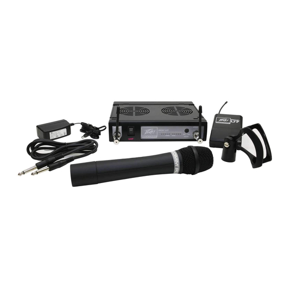
Summary of Contents for Peavey ProComm PCX-U7
- Page 1 ProComm ® ™ True Diversity UHF Wireless Receiver Operating Operat Manual Manu www.peavey.com www.peavey.com...
- Page 3 If your system is FCC Class B, the following applies: Note – These limits are designed to provide reasonable protection against harmful interference in a residential installation. This equipment generates, uses and can radiate radio frequency energy and, if not installed and used in accordance with the instructions, may cause harmful interference to radio communications.
- Page 4 Duración por Día en Horas Nivel de Sonido dBA, Respuesta Lenta 1 1 /2 1 /2 1 /4 o menos...
- Page 7 ENGLISH...
- Page 10 Plug Patterns Available: 120V North American 60 Hz Nema 5-15 NOTICE: Use the correct plug pattern for your Figure 1 area. If you 240 United Kingdom acquired the 50 Hz wrong plug, return unit to place of purchase. 220 Europlug 50 Hz CEE 7/16...
- Page 11 PIN 2 GND PIN 1 PIN 3...
- Page 13 IV Operation Instructions Squelch control...
- Page 15 Caution...
- Page 16 V. Handheld Wireless Microphone I. Unit Features and Functions 1. Grille: Protects cartridge and prevents breathing and wind POP noises. 2. Housing: Upper portion that is connected to the capsule module. Internally it holds the transmitter PCB and battery compartment. 3.
-
Page 17: Battery Insertion
II. BATTERY INSERTION III. OPERATING INSTRUCTIONS... - Page 18 Belt Pack Transmitter GAIN I. Unit Features and Functions 1. 3-pin Jack Input Connector: Connects to the Peavey ® ProComm 3-pin connector. Allow 5 different input configurations (See the five ways of connection on an AF input connection, page 20.) 2.
- Page 19 4. Gain Control: Adjusts the input gain to an appropriate level. 5. Transmitter Housing: Contains the PCB and battery. 6. Battery Status Indicator: battery status. 7. Power Switch: Switch to ON position for operation. Switch to OFF position when not in use. 8.
- Page 20 AF 4-Pin Input Connection Methods...
- Page 21 SPECIFICATIONS ™ 1. Overall: UHF PCX > > < ™ 2. Receiver: UHF PCX > > > ™ 3. Transmitter: UHF PCX <...
-
Page 22: Troubleshooting Guide
TROUBLESHOOTING GUIDE Symptom Distance Possible Cause Possible Solution No AF signal and no low transmitter battery replace battery RF signal voltage No AF signal and no long out of range move transmitter RF signal closer to receiver or obstecles No AF signal but microphone or other check input source normal RF signal... - Page 23 Logo referenced in Directive 2002/96/EC Annex IV (OJ(L)37/38,13.02.03 and defined in EN 50419: 2005 The bar is the symbol for marking of new waste and is applied only to equipment manufactured after 13 August 2005...
- Page 24 Features and specifications subject to change without notice. Peavey Electronics Corporation • 5022 Hartley Peavey Drive • Meridian • MS • 39305 (601) 483-5365 • FAX (601) 486-1278 • www.peavey.com ©2010 EX000126...
