Advertisement
Table of Contents
- 1 Heat Pump
- 2 Table of Contents
- 3 Introduction
- 4 Operation and Maintenance Instructions
- 5 Codes
- 6 Heat Pump
- 7 Evaporator & Condensate Drain
- 8 Copper Suction & Liquid Lines
- 9 Sweat-Type Connect Fittings
- 10 Refrigerant Piping
- 11 Electrical Hook-Up
- 12 Air Handler & Evaporator Matchups
- 13 Field Charging Procedures and Charts
- 14 Refrigerant Metering Devices
- 15 Defrost Control Description
- 16 Basic Sequence of Operation
- Download this manual
Advertisement
Table of Contents

Summary of Contents for Fedders CH1018BBD
-
Page 1: Heat Pump
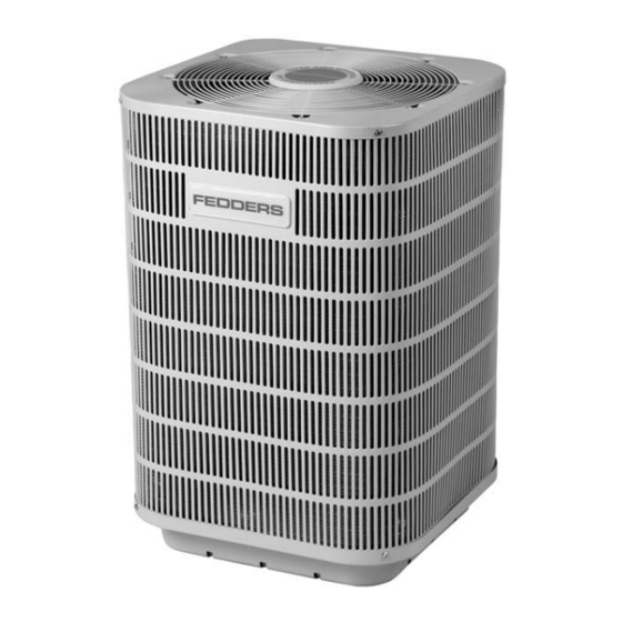
Installation, Operation and Maintenance MODEL CH10 & CH12 SERIES — 1.5 THRU 5 TON Split System High Efficiency Heat Pump REV. 1/20/04 23-23-0419N-001... -
Page 2: Table Of Contents
TABLE OF CONTENTS CONSUMER INFORMATION Introduction ........2 Operation and Maintenance Instructions . -
Page 3: Operation And Maintenance Instructions
OPERATION INSTRUCTIONS The heat pump system is a highly efficient way to heat and cool your home. During the summer months, the system transfers heat and humidity from your home to the outside. During the winter months, the heat pump will transfer heat from the outside to inside your home without drying the inside air. - Page 4 IMPORTANT: Wait at least 3 minutes after turning the heat pump off before trying to restart. If an attempt is made to start the compressor before the refrigerant pressures are equalized, the unit may fail to restart. An additional waiting period will then be required before restarting.
-
Page 5: Codes
INSTALLATION CODES: The installer SHALL comply with all local, state, and federal codes and/or regulations pertaining to this type of equipment and its installation. Such codes and/or regulations should take precedence over any recommendations contained herein in lieu of local codes. Installations SHALL be made in accordance with the National Electrical Code, local codes and recommendations made by the National Board of Fire Underwriters. -
Page 6: Copper Suction & Liquid Lines
COPPER SUCTION & LIQUID LINES REFER TO THE CHARTS ON PAGE 8 FOR THE RECOMMENDED TUBE O.D. SIZES ON LIQUID AND SUCTION LINES. Undersized line sets will increase the refrigerant pressure drop between the indoor evaporator and outdoor unit, resulting in a decrease in system capacity. -
Page 7: Refrigerant Piping
REFRIGERANT PIPING The following guidelines should be followed when installing refrigerant piping. 1. Run the tubing by the most direct route and support every few feet. Do not run the lines underground unless they are in a chase. 2. Insulate the vapor line to prevent sweating and line loss. In underground chases, the vapor line should be insulated to provide vibration isolation between the vapor and liquid line. -
Page 8: Air Handler & Evaporator Matchups
AIR HANDLER & EVAPORATOR MATCH-UPS The following indoor coils and air handlers are designed and approved for use with the CH series units. Refer to the installation instructions supplied with the indoor coils and air handler for installation detail. Some of the following information may not be included in those instructions and is specific to the application of the CH series heat pump systems. -
Page 9: Field Charging Procedures And Charts
FIELD CHARGING PROCEDURES Because each installation is different in terms of airflow, refrigerant line length, and configuration, the factory charge may not be correct for the application. To assure the best performance from the system, the refrigerant charge should be checked and adjusted if needed on each installation. - Page 10 SUPERHEAT CHARGING CHARTS FOR UNITS WITH PISTONS COOLING MODE OUTDOOR TEMPERATURE °F UPPER CURVE AT 80 DB, 67 WB (°F) ENTERING INDOOR TEMP. LOWER CURVE AT 70 DB, 60 WB (°F) ENTERING INDOOR TEMP. NOTE: All values are for reference only and may vary up or down. All heating values are with frost-free outdoor coil.
-
Page 11: Refrigerant Metering Devices
REFRIGERANT METERING DEVICES FIXED PISTON TYPE RESTRICTORS The indoor piston may require changing to match the outdoor unit. The correct indoor piston is shipped with each outdoor unit. Each coil has a marker strip, marked with the size of the factory-installed piston located on the coil liquid line. -
Page 12: Defrost Control Description
DEFROST CONTROL DESCRIPTION The outdoor unit uses an integrated defrost control to manage the following control functions of the system: 1. Off and on functions of the outdoor fan during the defrost and heating mode. 2. Off and on functions of the reversing valve during the defrost and heating mode.


Need help?
Do you have a question about the CH1018BBD and is the answer not in the manual?
Questions and answers