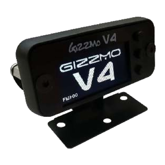
Summary of Contents for Gizzmo V4
- Page 1 Thank you for purchasing the Gizzmo V4 Boost Controller. This manual contains operating instructions and installation procedures that are needed for the fitment and operation of this product Instruction Manual V1.1...
- Page 2 V4 Controller THE V4 IS AN INFORMATIVE COMPETI TI ON GRADE BOOST CONTROLLER WI TH EVERYDAY FUNCTI ONALI TY. TAKI NG WHAT WE KNOW FROM A OVER A DECADE OF DEVELOPMENT, AND FROM LI STENI NG TO WHAT YOU, THE END USERS WANT, WE CONTINUALLY STRIVE TO GIVE YOU WHAT YOU NEED.
-
Page 3: Functions/ Specifications
ELECTRONICS Functions/ Specifications Number of boost memories 6 with individual gain settings Maximum boost 50psi (3.5bar) 32mhz 16bitRISC Processing Power Active Over Boost 5psi 50psi Closed with adjustable start Boost Control 9mm * 57mm * 26mm 11.8V size Operating Voltage (v) -
Page 4: Parts List
ELECTRONICS Parts List Thank you for purchasing t he Gizzm o I BC- R RPM dependent Boost Cont roller Boost Cont roller. This m anual cont ains operat ing inst ruct ions and inst allat ion procedures t hat are needed for t he fit t ing and operat ion of t his product ELECTRONICS.LTD... - Page 5 ELECTRONICS Warning/Caution Always connect t he wiring exact ly as described in t he inst ruct ion m anual. Disconnect t he negat ive t erm inal of t he bat t ery before proceeding wit h inst allat ion.
-
Page 6: Setup Menu Overview
Display: This option allows you to select if you want your boost settings and display in bar, psi or kpa Overboost: This option allows you to set a boost level at which the V4 will display a warning and cut boost in the event of a over boosting fault, this option also allows you to switch this feature off. -
Page 7: Solenoid Check
ELECTRONICS To Change Boost Memories To select the next memory simply press the DOWN button once The MEM: display will increment and the pressure display will show the target pressure for your new memory selected Then the running display... - Page 8 MULTI-SCRAMBLE The V4 has Gizzmo's multi-scramble feature. With this you can re-press the UP button or remote button whilst on scramble and the V4 will add another additional scramble duty and replenish the seconds. That's very confusing so here's an example.
- Page 9 Use UP and DOWN to set the limit that you would like to set at which the V4 warns you of an overboost situation and actively switches to minimum boost. Once you have set this press ENTER to save and exit to the running screen NOTE: When you first enter the overboost setup it may display 'OFF'.
-
Page 10: Input Trigger Setup
ELECTRONICS Input trigger Setup Press DOWN 3 times and Press ENTER once to access ENTER once to access the the menu screen input trigger selection Use UP and DOWN to highlight the selection you would like (descriptions below) and then... - Page 11 ELECTRONICS Anti Spike Setup Press DOWN 4 times and Press ENTER once to access ENTER once to continue the menu screen to the anti spike selection Use the UP and DOWN buttons to adjust the anti spike to the desired setting and then press ENTER to save and exit.
-
Page 12: Hard Reset
Another warning just to let you know all your setting will be erased perminently. Should you wish to continue, press UP once and ENTER. The V4 will restart with all the factory default settings as per when it was purchased CAUTION! If you do a hard reset, all user settings e.g. - Page 13 ENTER to continue duty will impact the boost, so At this point the V4 needs to learn the to the Duty setting. please read below. When you 'stable' boost for the set duty. Drive the...
- Page 14 1: BLACK Ground supply input looking INTO 2: RED 12V+ Power Supply input plug from V4 3: RED 12V+ Supply output from V4 to Solenoid 4: side YELLOW or BLUE Switch input to V4 5: BLACK Switching Ground output to Solenoid The Pressure port is t o be connect ed t o a direct pressure source at an inlet m anifold e.g.
- Page 15 ELECTRONICS Installation for an Internal Wastegate Connect t he t ails t o Port 2 and Port 3 of t he Solenoid Valve.
- Page 16 ELECTRONICS Installation for an E xternal Wastegate Connect t he t ails t o Port 1 and Port 2 of t he Solenoid Valve.
- Page 17 M e m or ie s The V4 has 6 m em ories in t ot al and can fast swit ch bet ween t hese. This m eans t hat when you select t he next m em ory t he boost will change im m ediat ely which is an advant age when changing m em ories whilst racing.
- Page 18 Sole n oid Su pe r visor The V4 const ant ly m onit ors t he boost cont roller solenoid out put channel t o ensure t hat t here are no m alfunct ions and should anyt hing go wrong t he V4 I MMEDI ATELY displays ‘SOLENOID FAULT’...
-
Page 19: About The Warranty
ELECTRONICS About The Warranty Gizzm o Elect ronics Lim it ed Lim it ed Warrant ies St at em ent Effect ive 1 January 2003 All Product s m anufact ured or dist ribut ed by Gizzm o Elect ronics are subj ect t o t he following Lim it ed Express...

Need help?
Do you have a question about the V4 and is the answer not in the manual?
Questions and answers