Table of Contents
Advertisement
Quick Links
Advertisement
Table of Contents

Related Manuals for Norsat ATOM Ku GaN 20W BUC


Summary of Contents for Norsat ATOM Ku GaN 20W BUC
- Page 1 Operator Manual ATOM Ku GaN 20/40/80W BUC&SSPA...
- Page 2 Norsat does not assume any liability arising out of the application or use of any product or circuit described herein. Norsat does not convey any license under its patent rights or the rights of others.
-
Page 3: Table Of Contents
J5 – RF output ......................36 2.10 Ground Connection ....................36 2.11 Fault Indicator / LED ....................36 ATOM Installation ....................37 Fans & Baseplate Cooling ..................37 Accessories ......................37 General Specifications .....................38 Standard Warranty ....................38 © Norsat International Inc. (“Norsat”) All Rights Reserved 2021-09-02 052910 Rev E... - Page 4 Table 2-3: J3 Pinouts for Ethernet Port ..................13 Table 2-4: DC Unit J4 Connector Pinout ...................24 Table 2-5: Command Summary ....................28 Table 3-1: General 20-40-80W ATOM Ku GaN Specifications ..........38 © Norsat International Inc. (“Norsat”) All Rights Reserved 2021-09-02 052910 Rev E...
-
Page 5: Overview
If this unit is a BUC, the IF input signal is upconverted to Ku-Band RF frequencies and then amplified to the specified power. SSPA – Solid State Power Amplifier If this unit is a SSPA, the RF input signal is amplified to the specified power. © Norsat International Inc. (“Norsat”) All Rights Reserved 2021-09-02 052910 Rev E... -
Page 6: Features
Power Connector – DC Units use a four-pin connector to provide power to the ATOM. See Section 2.6 J4 – DC Power for detailed description of pinouts. • Ground Terminal – a #10-32 screw is used to ground the chassis during use. © Norsat International Inc. (“Norsat”) All Rights Reserved 2021-09-02 052910 Rev E... -
Page 7: Cautions And Warnings
Apply voltage to the AC/DC input connector only as specified in the original configuration of this unit. Application of a voltage outside the specified range may cause the unit to become damaged or non-functional. © Norsat International Inc. (“Norsat”) All Rights Reserved 2021-09-02 052910 Rev E... -
Page 8: Introduction
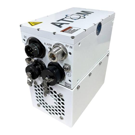
J4 – Four-pin circular shell size 12 Amphenol DC power connector • J6 – Ground terminal Figure 2-1: Input Connections for ATOM Ku GaN BUC Unit (N-Type Jack Shown) © Norsat International Inc. (“Norsat”) All Rights Reserved 2021-09-02 052910 Rev E... -
Page 9: Figure 2-2: Standard Waveguide Wr75 Output For Atom Ku Gan Unit
• J5 – WR75 waveguide RF output • J5 Option: WR62 waveguide RF output for wide band Figure 2-2: Standard Waveguide WR75 Output for ATOM Ku GaN Unit © Norsat International Inc. (“Norsat”) All Rights Reserved 2021-09-02 052910 Rev E... -
Page 10: J1 - If/Rf Inputs
Please contact the connector manufacturer for more information and/or refer to Amphenol® catalog 12- 070. Figure 2-3: J2 M&C Connector Pin Arrangement © Norsat International Inc. (“Norsat”) All Rights Reserved 2021-09-02 052910 Rev E... -
Page 11: Table 2-1: J2 Pinouts For Atom Configurations
Note that the ATOM mute state can also be controlled through the M&C interface. The software mute setting takes priority over the hardware pin. Refer to Section 2.7 for details. © Norsat International Inc. (“Norsat”) All Rights Reserved 2021-09-02 052910 Rev E... - Page 12 These pins form a standard RS-232 serial port. Pin F carries a signal from the host computer to the unit and Pin E carries a signal from the unit to the host computer. Pin G must be connected to the ground pin on the host computer. © Norsat International Inc. (“Norsat”) All Rights Reserved 2021-09-02 052910 Rev E...
-
Page 13: J3 - Ethernet Port
Figure 2-4: J3 Ethernet Connector Pin Arrangement Table 2-3: J3 Pinouts for Ethernet Port Connector Pin Standard Configuration Ethernet Tx- Ethernet Tx+ Open Ethernet Rx+ Ground Ethernet Rx- © Norsat International Inc. (“Norsat”) All Rights Reserved 2021-09-02 052910 Rev E... -
Page 14: Performing Firmware Update
2.0.0 or later. For firmware versions older than 2.0.0, use serial port connection with ATOMControl software. ATOMControl is a program designed for monitoring and controlling Norsat’s ATOM Series of BUCs and SSPAs. This software and user manual are available on the Norsat ATOM Series website. -
Page 15: Figure 2-6: Configuring A New Kermit Target For Tera Term Client
The New Connection dialog appears. Select TCP/IP, fill in Host IP and TCP Port# as 1649, and select Other for Service. Proceed with OK. Figure 2-7: Configuring Host, Port, and Service for Tera Term Client © Norsat International Inc. (“Norsat”) All Rights Reserved 2021-09-02 052910 Rev E... -
Page 16: Figure 2-8: Initiate Kermit File Send To The Target Atom Device
Ensure to select an official ATOM firmware image file with <.fwa> extension before sending. Always select an image file for a newer version of ATOM firmware. Contact customer service if you wish to downgrade firmware version. © Norsat International Inc. (“Norsat”) All Rights Reserved 2021-09-02 052910 Rev E... -
Page 17: Figure 2-9: Selecting Atom Firmware Image File For Upload To The Target Atom Device
Figure 2-9: Selecting ATOM Firmware Image File for Upload to the Target ATOM Device Select the Open or Send button. Tera Term will proceed with the firmware image upload to the ATOM device. © Norsat International Inc. (“Norsat”) All Rights Reserved 2021-09-02 052910 Rev E... -
Page 18: Figure 2-10: Kermit File Transfer In Progress
The transfer dialog closes when the transfer has completed. Power cycle the BUC or SSPA and wait 10 seconds for the new firmware to initiate and start. Verify the firmware version and restore the device setting using the latest version of ATOMControl software. © Norsat International Inc. (“Norsat”) All Rights Reserved 2021-09-02 052910 Rev E... -
Page 19: Figure 2-11: Firmware Version From Atomcontrol Fw Update Tab
Figure 2-11: Firmware Version from ATOMControl FW Update Tab Click the Browse button to show the find the Image File Selection Dialog. Figure 2-12: FW Image Browse Function © Norsat International Inc. (“Norsat”) All Rights Reserved 2021-09-02 052910 Rev E... -
Page 20: Figure 2-13: Image File Selection Dialog
Select the firmware image file from the Image File Selection Dialog for updating on the ATOM Ku GaN device. Click Open to confirm the selection. Figure 2-13: Image File Selection Dialog © Norsat International Inc. (“Norsat”) All Rights Reserved 2021-09-02 052910 Rev E... -
Page 21: Figure 2-14: Image File Confirmation And Start Update Function
Start Update function. Click the Start Update button to start the firmware update process. Figure 2-14: Image File Confirmation and Start Update Function © Norsat International Inc. (“Norsat”) All Rights Reserved 2021-09-02 052910 Rev E... -
Page 22: Figure 2-15: Progress Bar Indicates Firmware Update Progress
Do not switch off the ATOM-series device while firmware update is in progress. Figure 2-15: Progress Bar Indicates Firmware Update Progress © Norsat International Inc. (“Norsat”) All Rights Reserved 2021-09-02 052910 Rev E... -
Page 23: Figure 2-16: Confirmation Of Updated Firmware Version
ATOMControl. The status shows the new version of the firmware is running on the ATOM device. Figure 2-16: Confirmation of Updated Firmware Version Restore the device setting using the latest version of ATOMControl software. © Norsat International Inc. (“Norsat”) All Rights Reserved 2021-09-02 052910 Rev E... -
Page 24: J4 - Dc Power
The internal capacitance between the V+ and V- terminals is approximately 120 microfarads. © Norsat International Inc. (“Norsat”) All Rights Reserved 2021-09-02 052910 Rev E... -
Page 25: Serial Port Software Interface
This command returns the part number, software revision and serial number of the unit. getident ok pn BUC-KuG80W swver A 2.0.0_13603 sn 22378 getstatus This command instructs the unit to respond with fault flag, forward power and temperature. © Norsat International Inc. (“Norsat”) All Rights Reserved 2021-09-02 052910 Rev E... - Page 26 “err” if the current System Temperature is between the device’s temperature Trip Point and Reset Point. By default, Over Temperature fault is automatically cleared when the System Temperature drops below the device’s Temperature Reset Point. © Norsat International Inc. (“Norsat”) All Rights Reserved 2021-09-02 052910 Rev E...
- Page 27 Note that a response is enveloped by leading and trailing <CR><LF> characters. <CR> denotes a Carriage Return character, and <LF> denotes a Line Feed character. © Norsat International Inc. (“Norsat”) All Rights Reserved 2021-09-02 052910 Rev E...
-
Page 28: Table 2-5: Command Summary
<Over Input Fault> = 0 (input voltage ok) or 1 (input voltage too high) resettempfault None <CR><LF>ok<CR><LF> <CR><LF>err<CR><LF> (when system temperature is above trip point) setmute cmd (0|1) 0 = unmute <CR><LF>ok<CR><LF> 1 = mute © Norsat International Inc. (“Norsat”) All Rights Reserved 2021-09-02 052910 Rev E... -
Page 29: Figure 2-19: The Mute Logic Diagram
2. A mute command/signal is issued through the discrete SHUTDOWN line (Pin D of J2). 3. A fault condition exists. For mute priorities, software precedes over faults and hardware, and faults precedes over hardware. Figure 2-19: The Mute Logic Diagram © Norsat International Inc. (“Norsat”) All Rights Reserved 2021-09-02 052910 Rev E... -
Page 30: Ethernet Interface (Atomcontrol™ Web Interface & Atom Snmp Agent)
Interface. Ensure that a serial connection has been made to the device (refer to Figure 2-12 Setup Serial Port for details), and then use a terminal program or Norsat’s ATOMControl software to send the appropriate command(s) to the device. If a valid value is provided to the device, the device’s network services will be restarted automatically;... - Page 31 Command Line Interface. Ensure that a serial connection has been made to the device (refer to Figure 2-12 Setup Serial Port for details), and then use a terminal program or Norsat’s ATOMControl software to send the appropriate command to the device.
- Page 32 Command Line Interface. Ensure that a serial connection has been made to the device (refer to Figure 2- 12 Setup Serial Port for details), and then use a terminal program or Norsat’s ATOMControl software to send the appropriate command(s) to the device.
- Page 33 SNMP agent uses the same community string for both read and write Set the NMS/SNMP server to the same community string to access the Atom SNMP agent. Example commands and corresponding responses: setsnmpcommunity value AtomBUC<CR> <CR><LF>ok<CR><LF> © Norsat International Inc. (“Norsat”) All Rights Reserved 2021-09-02 052910 Rev E...
- Page 34 - sends traps when an over-input fault from the IF is detected on the ATOM device “all” - sends traps when any one or more of the above faults is detected on the ATOM device © Norsat International Inc. (“Norsat”) All Rights Reserved 2021-09-02 052910 Rev E...
- Page 35 0<CR> <CR><LF>ok<CR><LF> getsnmptrapoonfault<CR> <CR><LF>ok overtemp 0 pll 0 power 0 overinput 0<CR><LF> setsnmptraponfault all 1<CR> <CR><LF>ok<CR><LF> getsnmptrapoonfault<CR> <CR><LF>ok overtemp 1 pll 1 power 1 overinput 1<CR><LF> © Norsat International Inc. (“Norsat”) All Rights Reserved 2021-09-02 052910 Rev E...
-
Page 36: J5 - Rf Output
2.11 Fault Indicator / LED Description of Operation Norsat Ku GaN 20W, 40W and 80W are equipped in a general purpose Status LED signal. This signal is intended to give a visual aid of the status of the device. Modes of Operation The Status LED in the Front Panel of the devices will show three different statuses: STARTING, FAULT, and NO FAULTS. -
Page 37: Atom Installation
1 inch must be maintained around the air intake and exhaust during use. The fans are a field replaceable assembly; contact Norsat for details on replacement kits. If the unit is deployed inside a radome, ensure there is adequate cooling to remove heat and prevent the unit from overheating. -
Page 38: General Specifications
3.4 General Specifications Table 3-1 summarizes general specifications applicable to most 20/40/80W ATOM Ku GaN units. Please refer to the specific ATOM datasheet available on the Norsat website for complete unit specifications. Table 3-1: General 20-40-80W ATOM Ku GaN Specifications... -
Page 39: Figure A-1: 20-40-80W Ku Gan Buc/Sspa, Fan Cooled
Appendix A Mechanical Drawings Figure A-1: 20-40-80W Ku GaN BUC/SSPA, Fan Cooled © Norsat International Inc. (“Norsat”) All Rights Reserved 2021-09-02 052910 Rev E... -
Page 40: Figure A-2: 20-40-80W Ku Gan Buc/Sspa, Baseplate Cooled
Figure A-2: 20-40-80W Ku GaN BUC/SSPA, Baseplate Cooled © Norsat International Inc. (“Norsat”) All Rights Reserved 2021-09-02 052910 Rev E... - Page 41 Line Feed character (ASCII) M&C Monitor and Control Megahertz Millimeter Not Applicable Pulses per minute Radio Frequency Receive SSPA Solid State Power Amplifier Transmit Volt Volts Direct Current © Norsat International Inc. (“Norsat”) All Rights Reserved 2021-09-02 052910 Rev E...
- Page 42 Fortune 1000 companies. 110 – 4020 Viking Way | Richmond | British Columbia | Canada V6V 2L4 | support@norsat.com www.norsat.com © Norsat International Inc. (“Norsat”) All Rights Reserved 2021-09-02 052910 Rev E...