Table of Contents
Advertisement
Quick Links
L .
DRAKE COMPANY
R.
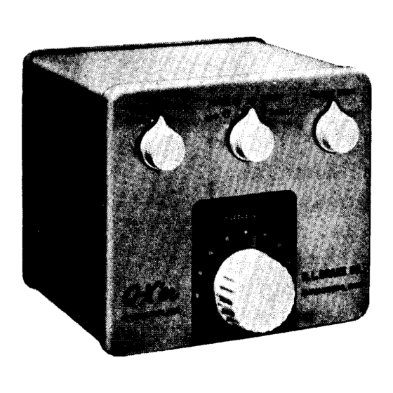
The Q-X'er is an attachment for a radio receiver.
to help discriminate between the wanted signal and interfering signals.
purpose is the same as for a crystal filter but the Q-X'er in operation is a
much more effective device.
follows
:
1.
NOTCH - With the selector switch set in the NOTCH position, a very
sharp rejection notch may be tuned across the pass band of the re-
ceiver to eliminate an, interfering carrier or heterodyne.
eral shape of the receiver pass band is unchanged and the notch is so
sharp that it is almost imperceptible in the audio of the desired sig-
nal. See Fig. (1).
2.
BOOST - With the selector switch set in the BOOST position again
the general shape of the receiver pass band is unchanged (though
lower in amplitude) but a sharp spike is imposed on top of the re-
sponse.
single frequency.
switch is used to boost the carrier of a weak phone or broadcast
station to prevent distortion due to selective fading, etc.
3.
PEAK - With the selector switch in the PEAK position the pass band
of the receiver is narrowed to a very selective response only a few
hundred cycles wide. Fig. (3).
The Q-X'er TUNING control can be used for a fine adjustment in
tuning in the signal.
note).
In principle of operation, the Q-X'er is simple.
vice shunted across an I. F. transformer 'in the receiver to act as a gate letting
through the desired frequencies and stopping the undesired frequencies.
Q-X'er achieves its performance through the use of an efficient, stable Q mul-
tiplier circuit.
mately 3000.
INSTRUCTIONS
I. GENERAL DESCRIPTION OF Q-X'ER
Three modes of operation are provided for as
This spike may be tuned across the pass band to boost any
See Fig. (2). Generally, this position of the
(Tuning here does not change the Beat Frequency
The Q-X'er acts just like a resonant circuit with a Q of approxi-
This accounts for its sharp peak or notch.
for
Q X ' er
This is ideal for C. W. reception.
It is a two terminal de-
-1-
Its main purpose is
The
The gen-
The
Advertisement
Table of Contents

Subscribe to Our Youtube Channel
Related Manuals for R.L.DRAKE Q-X'ER


Summary of Contents for R.L.DRAKE Q-X'ER
- Page 1 I. F. transformer ‘in the receiver to act as a gate letting through the desired frequencies and stopping the undesired frequencies. Q-X'er achieves its performance through the use of an efficient, stable Q mul- tiplier circuit.
- Page 2 Slightly turn in each direction the adjusting screw on the 455 KC I. F. cir- cuit to which the Q-X'er is to be connected to see that it is exactly peaked This tuned circuit is preferably the one at the plate to the rest of the set.
- Page 3 Ll (see fig. to peak the carrier at this point. Note These two coils in the Q-X'er are factory adjusted to 455 KC. Your adjustment takes care of any small devia- tion from 455 KC in the receiver I. F.
- Page 4 Notching Out a Heterodyne switch “OFF”. Tune in desired signal with Q-X’er Switch to _NOTCH and turn TUNING knob to the point where the heterodyne disappears. No need to touch the NOTCH ADJ. con- trol if it has been previously set properly. Note: The heterodyne is caused by a beat between the desired carrier and the interfering carrier.
- Page 5 IV. MAINTENANCE The Q-X’er circuit differs from other Q multiplier circuits published in that the degeneration tube is neutralized. This is factory adjusted by varying the spacing between a pair of ceramic disc capacitors. If these capacitors are moved, this adjustment is lost and operation is impaired in the notch position by a peak which will appear on one side of the notch.
- Page 6 Effect of NOTCH on Receiver Selectivity Fig. Fig.2 E f f e c t o f B O O S T F i g . 3 Effect o f PEAK...
- Page 7 4 7 K 150 K 5 0 0 m m f 2 . 2 - 0 1 m fd. Cap. values in unless otherwise n o t e d . PEAK o POWER PLUG viewed f r o m p i n e n d . S c h e m a t i c D i a g r a m o f Fig.
Need help?
Do you have a question about the Q-X'ER and is the answer not in the manual?
Questions and answers