Table of Contents
Advertisement
Quick Links
General Photonics Corp.
5228 Edison Ave.
Chino, CA 91710 USA
Document #: GP-UM-POS-002-21
网址:www.bonphot.com
POS – 002
Fiber-Optic Polarization Tracker
Operation Manual
September 27, 2013
邮箱:sales@bonphot.com
Ph: (909) 590-5473
Fax: (909) 902-5536
www.generalphotonics.com
电话:0512-62828421
Page 1 of 30
Advertisement
Table of Contents

Summary of Contents for General Photonics POS-002
- Page 1 POS – 002 Fiber-Optic Polarization Tracker Operation Manual September 27, 2013 General Photonics Corp. Ph: (909) 590-5473 5228 Edison Ave. Fax: (909) 902-5536 Chino, CA 91710 USA www.generalphotonics.com Document #: GP-UM-POS-002-21 Page 1 of 30 网址:www.bonphot.com 邮箱:sales@bonphot.com 电话:0512-62828421...
- Page 2 WARRANTY All of General Photonics’ products have been inspected and found to comply with our stringent quality assurance standards before shipping. If any damage occurs during shipment, please contact the carrier and inform us or our distributors as soon as possible.
- Page 3 Failure to comply with these precautions or with specific warnings elsewhere in this manual violates safety standards of design, manufacture, and intended use of the product. General Photonics Corp. assumes no liability for customers’ failure to comply with these requirements.
-
Page 4: Table Of Contents
Section 5. Application Examples ................... 26 5.1 PMD compensation....................26 5.2 Polarization Demultiplexing.................. 27 5.3 Coherence detection....................29 5.4 Polarization tracking for sensor system ..............29 Section 6. Technical Support ..................30 Document #: GP-UM-POS-002-21 Page 4 of 30 网址:www.bonphot.com 邮箱:sales@bonphot.com 电话:0512-62828421... -
Page 5: Section 1. Specifications
2. Other wavelengths and control algorithms may be available upon request. 3. The output power fluctuation caused by SOP fluctuation after passing through a polarizer. 4. Requires special cable (provided). Document #: GP-UM-POS-002-21 Page 5 of 30 网址:www.bonphot.com 邮箱:sales@bonphot.com 电话:0512-62828421... -
Page 6: Section 2. Overview
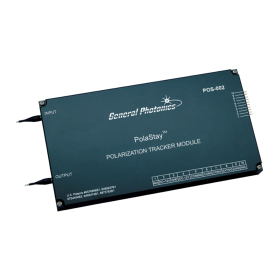
±50nm. Figure 1 POS-002 polarization tracker module for fiber-optic systems The operation of the POS-002 is based on a feedback system, as shown in Figure 2. It is internally controlled by a microprocessor. - Page 7 SOP is achieved. The POS-002 can also be factory configured to use external feedback control. In this case, the feedback signal is a DC or quasi-DC voltage generated by the user. This...
-
Page 8: Section 3. Feature Descriptions
All fiber connectors should be cleaned using industry standard cleaning methods before making connections to the POS-002. There are two output fiber options for POS-002 modules: PM output fiber and single mode (SM) output fiber, as shown in Figure 3 (a and b). The two output options have different features. -
Page 9: Electrical Features
• Never touch the boards inside the package without proper insulation and grounding. • The POS-002 is not user serviceable and can be serviced only by factory- authorized personnel. The power and communication connections and pin definitions for the POS-002 are listed below. -
Page 10: Section 4. Operation Instructions
EXTSIG (external feedback) Not Used Section 4. Operation Instructions: Electrical and optical connections are required during initial setup of the POS-002. The relevant safety precautions should be followed when making these connections. Warnings: • Never look into the light source fiber connector when light source is turned on. -
Page 11: Getting Started
4.2 Getting Started The POS-002 is enabled by default, with control settings at their default values, when it is powered on. The following steps describe the setup procedure: 1. The POS-002 has mounting holes at each corner of the enclosure. Use M3 screws to anchor the module in place. -
Page 12: Testing And Characterization
6. Turn on the DC power supplies. The POS-002 is enabled by default and will begin operation on power-up. 7. After the input fiber is connected and the optical power is turned on, the POS-002 will automatically stabilize the input SOP to a linearly polarized output SOP (internal optical feedback option) or optimize the SOP to either maximize or minimize the error signal (external electrical feedback option). -
Page 13: Remote Control And Programming
DB9 connector on the connection cable). The POS-002 comes with two connection cables. One has a 10-pin connector on one side to connect to the POS-002. On the other side of that cable are labeled wires for the power and external signal connections, and a 3-pin connector to connect to the RS-232 connection cable. -
Page 14: Remote Operation And Commands
4.4.2 Remote operation and commands General Photonics provides a test program for remote control of the POS-002. See section 4.4.4 for installation and operation instructions for the program. The following steps and commands are recommended for remote operation of the POS- 002 using the RS-232 communication port. - Page 15 Missing end character Missing parameter Invalid syntax found in command string Invalid mode command. String of characters too long(>buffer limit) Light power too high Light power too low parameter outside allowed range Document #: GP-UM-POS-002-21 Page 15 of 30 网址:www.bonphot.com 邮箱:sales@bonphot.com 电话:0512-62828421...
- Page 16 Figure 7 POS-002 response to discontinuous change in input polarization state (using default control settings and fixed step size mode) Figure 7 shows the response of the POS-002 to a single discontinuous change in the input polarization state, using the default control parameter settings. The red line is the input polarization, and the blue line is the POS-002 output.
- Page 17 In fixed step size mode, the POS-002 uses a constant step size, set using the *STS xx# command, for its polarization adjustments.
- Page 18 Choosing a larger step size will reduce the response time, but can also increase noise. Figure 10 shows the response of the POS-002 to the same discontinuous change in the input polarization state as in Figure 7, but with a low threshold setting and a step size setting larger than the default value.
- Page 19 POS-002, or the electronics used to generate the feedback signal may need time to respond to polarization changes made by the controller. The DLY command adds a delay offset to the period between a polarization controller step and the next read of the feedback signal, increasing the effective cycle time to 26 + 0.5*xxx + 2*(yy −...
- Page 20 Figure 13 shows the response of the POS-002, using a delay setting of 50, to the same discontinuous change in the input polarization state used in Figure 7. It can be seen that the time per step, and thus the cumulative response time, is longer. Figure 11 and 12 provide a closeup comparison of the response time with different delay settings.
- Page 21 POS- 002) to xx * 1.22 mV. For example, if for a given laser source, the POS-002 stabilizes the SOP such that the feedback signal reaches a maximum of 4V, then, with the threshold level at the default setting, as long as the feedback signal remains higher than 4V- 0.00122V = 3.99878V, the POS-002 will not actively change the polarization.
-
Page 22: Rs-232 Troubleshooting
5. Check commands: command should begin with “*” and end with “#” or “?”” 4.4.4 LabView control program The command list in Table 2 can be used to write control programs for the Pos-002. General Photonics provides a sample control program that can be used as a base for customization by the user. - Page 23 Stop the program first (stop sign or Ctrl +. ), then choose the correct port, if necessary. Note that ASRL1:INSTR is the same as COM1. Use the white arrow or Ctrl+R to restart the program. Document #: GP-UM-POS-002-21 Page 23 of 30 网址:www.bonphot.com 邮箱:sales@bonphot.com...
- Page 24 Command buttons (bottom left of screen): Clicking a command button from this screen sends the corresponding command to the POS-002. Command Response box: Displays the POS-002’s response to the command. See Table 2 and Table 3 for more detail on responses to version/status query commands.
- Page 25 Response should be “*E00#” if the command was successfully received. Power CK button: Checks input light level on an internal feedback POS-002. Light Ready: Indicator light turns on after “Power CK” is clicked if the light level is within range.
-
Page 26: Section 5. Application Examples
BER detected before FEC inside the receiver. The user converts the error signal into an analog signal between 0.5 and 4.6V volts and feeds it back to the POS-002-E. The polarization tracker then either maximizes or minimizes the error signal to achieve PMD compensation. -
Page 27: Polarization Demultiplexing
0.5 to 4.6V feedback signal for the POS-002-E. The detected pilot tone will be maximized when the two polarization channels are properly separated. The polarization tracker then automatically maximizes the feedback signal to separate the two polarization channels. - Page 28 A simple circuit can be used to convert the noise channel power difference into a 0.5 to 4.6V feedback signal for the POS-002-E. The polarization tracker then automatically maximizes the feedback signal to effectively separate the two polarization channels.
-
Page 29: Coherence Detection
In a coherent detection system, the states of polarization of the signal and local oscillator must be the same in order to maximize signal to noise ratio. A POS-002-I can be used to stabilize the SOP of the signal after it propagates through the transmission fiber. The SOP of the output of the polarization tracker is linear and aligned with the slow axis of the PM fiber pigtail and will beat with the local oscillator. -
Page 30: Section 6. Technical Support
Section 6. Technical Support General Photonics is committed to high quality standards and customer satisfaction. For any questions regarding the quality and the use of the POS-002, or future suggestions, please contact General Photonics Corporation at (909)-590-5473 (telephone) or (909)- 902-5536 (fax), or by e-mail at info@generalphotonics.com.
Need help?
Do you have a question about the POS-002 and is the answer not in the manual?
Questions and answers