
Summary of Contents for mycom IMS20-210
- Page 1 No.QT33-04005F Driver for 2 phase stepping motor IMS20-210(L) 【User’s manual】 MYCOM, INC.
- Page 2 No.QT33-04005F Attention on safety Please read this user’s manual carefully before using and use rightly. The purpose of this attention is to protect users or others from the injure, damage or loss of property in advance and use this product rightly and safely. This danger shows the possibility that the user may die or get serious injures by fire or electrical shock and the contents which are high DANGER...
- Page 3 ● Avoid dews to form. It may cause a short circuit or malfunctions. ● MYCOM is, in no way, responsible for any damages or malfunctions that are caused by user’s repair or modifications on this driver. If the user performed these initiations and the driver does not work satisfactory, a warranty will not be provided.
-
Page 4: Table Of Contents
No.QT33-04005F Index 1. Specification of driver・・・・・・・・・・・・・・・・・・・・・・・・・・・・・・・・・・・・・・・・・・・・・・・・・・・・・・・・・・・・・・・・ 1 2. Model number and Factory default・・・・・・・・・・・・・・・・・・・・・・・・・・・・・・・・・・・・・・・・・・・・・・・・・・・・ 2 2-1. Model number of set ・・・・・・・・・・・・・・・・・・・・・・・・・・・・・・・・・・・・・・・・・・・・・・・・・・・・・・・・・・・・・ 2 2-2. Model number of driver ・・・・・・・・・・・・・・・・・・・・・・・・・・・・・・・・・・・・・・・・・・・・・・・・・・・・・・・・・・ 2 2-3. Factory default・・・・・・・・・・・・・・・・・・・・・・・・・・・・・・・・・・・・・・・・・・・・・・・・・・・・・・・・・・・・・・・・・・ 2 3. Pulse wave ・・・・・・・・・・・・・・・・・・・・・・・・・・・・・・・・・・・・・・・・・・・・・・・・・・・・・・・・・・・・・・・・・・・・・・・・・ 3 3-1. Input pulse type・・・・・・・・・・・・・・・・・・・・・・・・・・・・・・・・・・・・・・・・・・・・・・・・・・・・・・・・・・・・・・・・・ 3 3-2. -
Page 5: Specification Of Driver
No.QT33-04005F 1. Specification of driver Model number IMS20-210(L) Power source Single phase AC100-120V±10%, 50/60Hz 240 VA or less Power consumption Driving type Bi-polar type Driving current Max. 2.0A (Total output current) Correspondence Uni-polar type :Max. 2.0A/phase motor current Bi-polar type :Max. 1.0A/phase... -
Page 6: Model Number And Factory Default
Driver model (Uni-polar type) currrent marking 243A(B) PF243-A(B) 0.9A/phase 244A(B) PF244-A(B) 1.2A/phase 245A(B) PF245-A(B) IMS20-210 approved IMS20-210L 264A(B) PF264-A(B) 265A(B) PF265-A(B) 2.0A/phase 268A(B) PF268-A(B) ・Please use our CE marked motor. ・Please use the motor in safety condition after careful confirmation of... -
Page 7: Pulse Wave
No.QT33-04005F 3. Pulse wave 3-1. Input pulse type ・2 pulses type Timing chart MOTOR CW+ Pulse signal CW− CCW+ Pulse signal CCW− Motor starts to rotate by rising edge(↑) of CCW or CW signal. ・1 pulse type Timing chart MOTOR PULSE+ Pulse signal PULSE−... -
Page 8: Pulse Waveform
No.QT33-04005F 3-2. Pulse waveform ・2 pulses type CW signal CCW signal t1: 6μsec or longer t2:10μsec or longer t3: 2μsec or shorter t4:20μsec or longer ・ section shows ON status(turn on of photo coupler) of input circuit photo coupler. ・ Motor starts to rotate by rising edge(↑) of CCW or CW signal. ・1 pulse type Pulse signal Direction signal t1 : 6μsec or longer t2 :10μsec or longer t3 : 2μsec or shorter t4,t5:20μsec or longer ・ section shows ON status(turn on of photo coupler) of input circuit photo coupler. ・ Motor starts to rotate by rising edge(↑) of pulse signal. ・ Direction signal input is to rotate CW direction by inputting pulse signal at ON status. Also if pulse is inputted at OFF status, motor rotates to CCW direction. ・ Signal name of product uses pulse signal as CW input and direction signal as CCW input. Attention 1. If the signal exceeds the voltage of DC5V in use, please insert the series resistor near to output terminal(connector) of using controller so that 10mA current pass. Input voltage−5V Value of resistor to be inserted(Ω)= −Register value of wiring(Ω) 10mA 2. Current down function is invalid if the photo coupler of pulse input keeps ON status at stopping. - 4 -... -
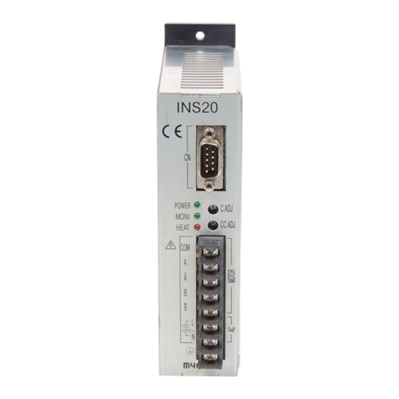
Page 9: Each Part Name And Functions
No.QT33-04005F 4. Each part name and functions 4-1. Each part name ① Power display LED I M S 2 0 This lights up on during power on. ② Overheat display LED This rights on when the temperature of internal hea-sink rises and becomes overheat ④... -
Page 10: Description Of Function
No.QT33-04005F 4-2. Description of function 4-2-1. Power indicator LED (POWER) This rights on during power on. 4-2-2. Overheat indicator LED (HEAT) This rights on when the temperature of internal heat-sink rises and becomes overheat condition. Then a signal is outputted to the HEAT output of CN. 4-2-3. -
Page 11: Signal I/O Connector (Cn)
No.QT33-04005F 4-2-7. Signal I/O connector (CN) This is to be connected with driving pulse, current off signal and various monitor signals. Connector pin assignment CW− MONI+ CCW+ HEAT+ CCW− COM− (Front panel side) Connector combination 9 pin D-sub connector Socket type Connector : OMRON, XM2D-0901 equivalent Hood : OMRON, XM2S-0911 equivalent(M2.6×0.45)... -
Page 12: Example Of Wiring
No.QT33-04005F 5. Example of wiring I MS2 0‑ 21 0(L ) Tw iste d p air wir e C ontr oll er + 5 V ( SNC ser ies ) 2‑ ph as e m ot or Ph oto cou ple r CW... -
Page 13: Tightening Torque For Terminal Block
・Do not use driver outside of control box. This unit is designed for the following condition. Over voltage category: Category II, Material group III Pollution degree: Class 2 Protection structure: IP20(IMS20-210), IP00(IMS20-210L) Protection against electric shock: Class I component ・Fix driver on heat conductive metal plate tightly. -
Page 14: Dimension
No.QT33-04005F 7. Dimension 7-1. Dimension I M S 2 0 P O W E R H E A T C . A D J 10 0‑ 12 0V〜 16MAX A(Bottom) B(Reverse) name plate Unit : mm, The screw head is not included. - 10... -
Page 15: Dimension Of Metal Bracket(Option)
No.QT33-04005F 7-2. Dimension of metal bracket(Option) Dimension when option is assembled. A(Bottom) B(Reverse) 31.5 26.5 Unit : mm - 11 -... - Page 16 No.QT33-04005F 8. Option It is available to supply the following optional cables which have covering connector at the one side. ・CN: Pulse cable Model number :OPC-DS9P15 Connector : 9pin D-sub Cable : More than AWG28 multi-core twisted pairs cable with shield 1.5m 1500mm ‑10 Connect the unused cables with the ground of the upper.
- Page 17 Please understand that we may make modifications to our products without notification in order to improve the capabilities and external appearance of our products. MYCOM, INC. 1-29, Goryoohara, Nishikyo-ku, Kyoto 615-8245, Japan TEL: 81-75-382-1580 FAX : 81-75-382-1570 E-mail support@mycom-japan.co.jp Home Page : http//www.mycom-japan.co.jp/...
Need help?
Do you have a question about the IMS20-210 and is the answer not in the manual?
Questions and answers