Advertisement
1.1 Description
The 5865-3 and 5865-4 are LED Annunciators that provide you with 30 programmable LED's (15 red, 15 yellow). 5865 connects to the panel via
the SBUS.
1.1.1 Specifications
Max. Line Resistance
Max. Alarm Current
Standby Current
Max. Voltage
Operating Temperature
Indoor Use Only
1.2 Mounting the 5865-3
The 5865-3 mounts into a standard 3-gang electrical box. Follow these steps to mount the 5865-3:
1.
Make sure that the 5865-3 is properly wired to the control panel. See Figure 1.2.
2.
Place the 5865-3 into the 3-gang electrical box. See Figure 1.1.
3.
Place cover plate over the top of the 5865-3 and align the holes. See Figure 1.1.
4.
Insert the six cover plate screws into six screw holes on the 3-gang electrical box.
5.
Screw the six cover plate screws all the way in until the cover plate fits firmly against the 5865-3 and the electrical box. Do Not over tighten.
1.3 Mounting the 5865-4
The 5865-4 mounts into a standard 4-gang electrical box. Use the same procedure as used for mounting the 5865-3.
NOTE:
The 5865-4 uses 8 cover plate screws.
50
145mA
35mA
24VDC
0° to 49° C
(32° to 120° F)
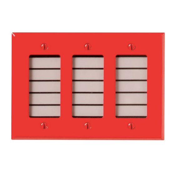
cover
plate
screw
Figure 1.1 : 5865-3 Mounting
5865-3 and 5865-4 LED Annunciator
Product Installation Document
PN 151088:D 03/12/2018
3-gang
electrical box
5865-3
cover plate
ECN 18-0103
Advertisement
Table of Contents

Related Manuals for SILENT KNIGHT 5865-3


Summary of Contents for SILENT KNIGHT 5865-3
- Page 1 Insert the six cover plate screws into six screw holes on the 3-gang electrical box. Screw the six cover plate screws all the way in until the cover plate fits firmly against the 5865-3 and the electrical box. Do Not over tighten.
- Page 2 Installation and wiring of these devices must be done in accordance with NFPA 72 and local ordinances. Terminate the wiring as shown in Figure 1.2. Also refer to Table 1.1 for wire connections. supervised power limited Figure 1.2 5865-3 or 5864-4 Connection to the FACP FACP Terminals 5865-3 & 5865-4 Terminals Label Table 1.1 Wire Connections...
Need help?
Do you have a question about the 5865-3 and is the answer not in the manual?
Questions and answers