Table of Contents
Advertisement
Quick Links
Product Manual
Description
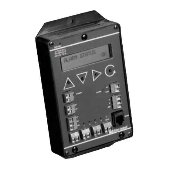
The SZ1145 is a microprocessor-based monitoring and
alarm interface designed to monitor up to four 1000 Ω
platinum temperature sensor inputs and up to two 4-20
mA inputs. The RTD inputs, scaled 20 to 120°F (-6.7 to
48.9°C ), are suitable for monitoring temperatures in this
range. If any of these inputs exceed their high or low
limits, the alarm output relay is energized.
Features
• Stand-alone or network operation
• Independently programmable high and low limits for
each input
• Independently programmable manual or automatic
alarm reset
• Change of state factor with programmable hysteresis
• 32 character LCD display
• Two Status LEDs
• Relay output to activate additional auxiliary communi-
cation devices or external alarm circuit
• Direct RTD temperature inputs
• Two 4-20 mA analog inputs suitable for a broad variety
of transducers
Mounting
The SZ1145 is designed for mounting using two #10
sheet metal screws.
2800 LAURA LANE • MIDDLETON, WI 53562 • (800) 288-9383 • FAX (608) 836-9044 • www.tcsbasys.com
SZ1145
General Purpose Monitor
Contents
. . . . . . . . . . . . . . . . . . . . . . . . . . . . . . . . . .
. . . . . . . . . . . . . . . . . . . . . . . . . . . . . . . . . . . .
Mounting. . . . . . . . . . . . . . . . . . . . . . . . . . . . . . . . . . . .
. . . . . . . . . . . . . . . . . . . . . . . . . . . . . . . . . . . . . .
. . . . . . . . . . . . . . . . . . . . . . . . . . . . . . . .
. . . . . . . . . . . . . . . . . . . . . . . . . . . . . . . . . . .
. . . . . . . . . . . . . . . . . . . . . . . . . . . . . .
R
1
Communicating Controls
1
1
1
2
3
5
. . . . . . . . . . . . . . . . . . . .
6
8
Advertisement
Table of Contents

Subscribe to Our Youtube Channel
Summary of Contents for TCS Basys Controls SZ1145
- Page 1 • Two 4-20 mA analog inputs suitable for a broad variety of transducers Mounting The SZ1145 is designed for mounting using two #10 sheet metal screws. 2800 LAURA LANE • MIDDLETON, WI 53562 • (800) 288-9383 • FAX (608) 836-9044 • www.tcsbasys.com...
- Page 2 Wiring POWERING THE SZ1145 The SZ1145 is powered from 24 VAC +/- 20 %. The SZ1145 uses terminal designations for wiring. See diagram below. Caution: Do not connect to 120 VAC. When multiple TCS/Basys Controls devices are using a single...
- Page 3 Temp1 input alarm function. ALARM? The SZ1145 may be programmed through the display and keypad, or with a PC. If programming with a PC, the following must be set Temp1 Alarm Low Limit Screen. Enter through the keypad prior to programming: a low limit temperature setting.
- Page 4 (This screen is not shown if the Temp4 alarm is not enabled.) AI2 Decimal Point Screen. For display purposes, the SZ1145 allows a deci- TEMP4 ALARM Temp4 Alarm Hysteresis Screen. SET AI2 DECIMAL mal point to be turned on.
- Page 5 The decimal point is for display pur- the programming mode. The default is CODE: poses only on the SZ1145 display. For example if you 248. are sensing differential pressure from 0 to 1", you could scale the analog input to be 0 to 100 and then turn on ALARM STATUS Main Monitoring Screen.
- Page 6 There is an Alarm Delay Wait Time which, when set, applied to all analog inputs (TEMP1-4 and AI1&2). If no Whenever an input of the SZ1145 is in an alarm condi- delay is desired, set the delay time to 0 minutes and tion, based on its settings, the SZ1145 will indicate the 0 seconds.
- Page 7 3. Take note of the current temperature and other input tive temperature coefficient and the reading will change readings. If the SZ1145 will be used only for monitor- 2.16 Ω per °F. If the actual temperature was 70°F the ing, and the readings appear to be correct, you are reading would be 1082 Ω.
- Page 8 DI1 & DI2 Alarm Screen. Shows the DI1 ALARM ON LED Description and/or DI2 alarm condition if either is in alarm. ALARM ON PROGRAM/DATA This LED will be lit when the controller is within the programming setup menus. It will blink when the unit is being accessed by a PC.
Need help?
Do you have a question about the SZ1145 and is the answer not in the manual?
Questions and answers