
Summary of Contents for HEINRICH DVA8-500W
- Page 1 HEINRICH DVA8-500W Controller of Wall Mounted EVAC System USER MANUAL Before using the system, please read this manual carefully...
- Page 2 Notification WARNING To ensure the reliability of the equipment and the safety of personnel, please observe the following when installing, using and maintaining: ● If any of the following conditions are found, please immediately turn off the power, plug out and quickly contact your nearest dealer. Do not continue using this unit, which may cause a fire or electric shock.
- Page 3 ● This product uses a power plug or appliance input socket as a disconnecting device with the power supply, and must be disconnected if necessary for safety reasons. ● This equipment is only suitable for safe use at altitudes under 2000 meters. Precautions 1.
- Page 4 5. Agreement Please strictly follow the instructions in this manual. The software, hardware and appearance of this product will be upgraded and updated continually. The above changes will be made without notice. Non-professional maintenance personnel, do not remove the product, to avoid damage and electric shock.
-
Page 5: Table Of Contents
INDEX 1 Product Design Sketch ......................... 1 1.1 Dva8-500w D esign ketch ............................2 Main Function Introduction ....................... 2 Dva8-500w F eatures ............................3 Main Technical Parameters Of The Equipment ..............3 3.1 E lectrical ndicators ............................... 3.2 P erformance ndicators ............................ -
Page 6: Product Design Sketch
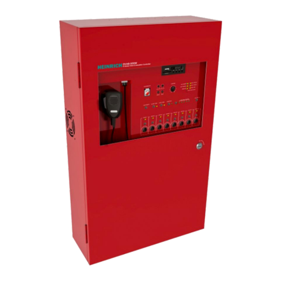
1 . Product Design Sketch 1.1 DVA8-500W Design Sketch Image 1- 1 DVA8-500W Design Sketch... -
Page 7: Main Function Introduction
2 . Main Function Introduction 2.1 DVA8-500W Features ◼ Built-in 650W high-efficiency digital power amplifier, integrated 8 power A + B independent dual-speaker loop zone output, each zone has independent LED indicator, independent output control buttons and volume adjustment; ◼ 4 audio balanced input interfaces for playing any audio source in the zones ◼... -
Page 8: Main Technical Parameters Of The Equipment
3 . Main Technical parameters of the equipment 3.1 Electrical Indicators Power supply ⚫ Voltage ~ 220-240V±20%, 50-60Hz ⚫ Fuse specifications :10A slow breaking type 3.2 Performance Indicators Analog audio MIC. input ⚫ Sensitivity ±2.5mV ⚫ Frequency response 200Hz~10kHz ⚫... - Page 9 Mechanical Indicators ⚫ Size (L × W × H) :726*440*180.7mm ⚫ Net weight:24.5Kg ⚫ Installation:Wall Mounted ⚫ Color :Fireman's Red Environmental Requirements ⚫ Operating temperature +5℃~ +40℃ ⚫ Storage temperature -20℃~ +70℃ ⚫ Relative temperature <95%...
-
Page 10: Device Function Description
4 . Device Function Description 4.1 The introduction of the front panel of DVA8-500W is as below Image 4- 1 DVA8-500W Sketch of Front Panel... -
Page 11: Function Description Of Front Panel
4.2 Function Description of Front Panel Image 4- 2 DVA8-500W Sketch of Front Panel ◼ Indicator and status description: ➢ ①AC POWER: AC indicator,green on means normal , yellow on means AC power off. ➢ ②DC POWER: DC power indicator light, green o n means 24V power connected , yellow on means out of connect to DC 24V, light off means without configuration for DC power. - Page 12 If indicator is red, means the zone is playing emergency voice, Alarm Mic paging or PTT paging. If indicator is yellow, means the zone is short circuit or open circuit failure If indicator is off, means the zone status is normal; ➢...
-
Page 13: Function Description Of Rear Panel
◼ ㉔Zone volume adjustment knob. ◼ ㉕Handheld microphone interface. 4.3 Function Description of Rear Panel Image 4- 4 DVA8-500W Sketch of Rear Panel 1. Radio antenna interface; 2. Local line balance audio input connectors 1~ 4, and its input volume adjustment knob. - Page 14 8. SYS CONTROL: ➢ System Fault Output—When the system is running normally, the system fault output is turned off; after the fault and power is cut off, the system fault output is turned on; ➢ System EVAC Output—Fire alarm output, this port will close when a fire alarm is triggered;...
-
Page 15: Operation Instructions
5 . Operation Instructions 5.1 Self-test function 1. Power-on self-test: 1、Connect to AC power supply. 2、Turn the power switch to the ON position. 3、When the host is power-on, can hear the relay sounds in turn(Self-test). 4、Panel indicator will show the system’s current status. 2. - Page 16 3. The way of exit emergency mode--Fire alarm reset By press red with a large button on host panel By fire linkage node input control, As shown in Figure 5-1: Fire alarm reset mode Image5-1 Fire alarm reset node schematic...
-
Page 17: Local Audio Source Play
5.3 Local audio source play ◼ Audio source selection Audio Source selection button Press the audio source selection button to select the source channel. The corresponding indicator light will indicates the currently selected audio source. For example, LINE5 indicator correspond to MP3. 1. -
Page 18: Ptt Paging
5.4 PTT Paging Sharing MP3 Module PTT Button Press the EMERGENCY button, then press the button on the PTT microphone to turn on the corresponding zone paging (Require to configure on PC). You can speak after the reminder tone. Please do not release the button during the speaking or it will automatically turn off paging and make a tone. -
Page 19: Line Detection
5.5 Line detection Detection accuracy:15%、20%、25%、30%、35% Minimum detection power: 10W Maximum detection power: 650W Installation of the new device requires sampling the speaker impedance, the specific operation is as follows: 1. Install new equipment , connect speakers for each zone. 2. Press impedance detection button on the rear panel, the system will be connected to each zone to sample the load, during sample period can hear during the relay inhalation of the sound, when the lights all off, indicating that the load sampling success. -
Page 20: Olume Control
5.6 Volume control Zone 1 ~ 8 volume adjustment PTT volume adjustment Monitor volume adjustment Treble adjustment Bass adjustment Host volume Host volume control is control the volume of the entire machine, the adjustment will affect the 1 ~ 8 zone volume. Zone volume adjustment only adjusts the corresponding zone volume, does not affect other zones. -
Page 21: Ip Address Reset
5.7 IP address Reset IP address Reset button Press the IP reset button to reset the host IP address: 192.168.14.49. 5.8 Impedance detection function of zone output circuit Zone impedance sampling button Calibrate current line impedance before do the line detection, connect the speaker circuit then press impedance detection calibrate button, the host will perform impedance calibration of the speaker circuit. -
Page 22: Spare 24V Accumulator Switching Function
5.9 Spare 24V Accumulator Switching Function When connecting to at least 24V/33AH battery, and the PC software is configured with 24V DC, the indicator light will turn green. When the mains plug is unplugged, it will automatically switch to the 24V power supply mode. 5.10 Extended Host Address Setting DIP Switch of Extended Host Address Extended machine address comparison table:... -
Page 23: Set The Device To Slave Mode
5.11 Set the device to slave mode When the device is set to slave, that is, the device is used as an extended partition, the slave part function cannot be used. 1. Functions are invalid when as slave: panel independent MP3 module, panel PTT microphone and PTT volume potentiometer, panel emergency switch, panel EVAC/ALERT button and indicator light, CAN port in the cabinet, LAN port in the cabinet and IP reset button , antenna port. -
Page 24: Indicator Light Status Comparison Table
5.13 Indicator Light Status Comparison Table (Yellow) (Green) (Red) (Extinguish) Power AC power Power × × Indicator Malfunction Supply Normal Light Power DC 24V DC 24V Power × Malfunction Indicator Light Normal Configuration PAGING The remote mic × × Normal Indicator Light is paging Always-on:... - Page 25 SYS FAULT: Yellow indicates that the system has failed. Flicker indicates a new fault in the system. Off indicates normal. NET FAULT: Green indicates that the network communication is normal, and yellow indicates that the network communication is faulty; EMC MIC: Red indicates that PTT is paging, yellow indicates PTT malfunction, extinguish indicates normal, red flicker indicates PTT is occupied by fire MIC, and paging cannot be initiated.
Need help?
Do you have a question about the DVA8-500W and is the answer not in the manual?
Questions and answers