
Summary of Contents for Huaming CVIII 350Y
- Page 1 CV & SV On-Load Tap-changer Operating Instructions HM 0.460.001-02.05/2021 IMPORTANT: Please read this manual carefully before using the tap-changer and save it for reference.
- Page 2 Huaming has no liability for any damage due to incorrect interpretation of this document. Keep this manual at hand for future use and in case of any question, please contact Huaming. Prior to using the on-load tap-changer, make sure to pay attention to the following items: 1.Tap-changer and motor drive unit must be connected on the same position.
-
Page 3: Table Of Contents
HM0.460.001 TABLE OF CONTESTS 1.Foreword ..........................5 1.1 Safety ..............................5 1.2 Notation and conventions ........................5 1.3 Safety precautions ..........................6 2. General ..........................7 3. Technical data ........................9 3.1 Table of technical data ........................9 3.2 Operation conditions ........................10 4. - Page 4 HM0.460.001 13.4 Notice .............................. 53 14. Appendix ......................... 54...
-
Page 5: Foreword
HM0.460.001 1.Foreword This instruction manual is a comprehensive description of product transportation, installation, commissioning, test and maintenance. It is intended for trained and qualified staff related to transformer production, testing and quality assurance, and has reference value for transformer design and operation personnel. 1.1 Safety Safety instructions are explained in this manual. -
Page 6: Safety Precautions
HM0.460.001 NOTE! The blue note symbol indicates important information that must be noted. 1.3 Safety precautions Precaution Action Always unplug a device before inspection. Stay away from high-voltage Electric shock equipment and wear protective clothing. Collect used transformer oil in dedicated drums. Keep it away from Transformer oil flames or sparks. -
Page 7: General
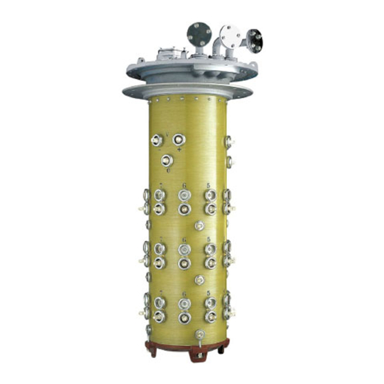
CMA7 or SHM-D motor drive unit through the worm gear reducer, horizontal drive shaft, bevel gear box, and vertical drive shaft, so as to achieve the purpose of tap change. NOTE! Special design is available. Please contact Huaming for further information. - Page 8 HM0.460.001 Figure 1 Overview of tap-changer 1. Pipe bend 2. Upper gear unit 3. Horizontal drive shaft 4. Bevel gearbox 5. Vertical drive shaft 6. Motor drive unit 7. Oil compartment Table 3 List of tap-changer components...
-
Page 9: Technical Data
HM0.460.001 3. Technical data CV/SV tap-changer complies with IEC 60214-1: 2014 standard. 3.1 Table of technical data CVIII 350Y CVIII 350D Description CVI 350 SVIII 500Y SVIII 500D CVI 700 Max. rated through current (A) Rated frequency (Hz) 50 or 60... -
Page 10: Operation Conditions
4). No sever dust and other explosive or corrosive gases on the installation site. CAUTION! Do not store the tap-changer or motor drive unit in a place with high humidity (≥85%). This will cause condensation. NOTE! Special design is available to meet particular environment conditions. Please contact Huaming for further information. -
Page 11: Type Designation
HM0.460.001 4. Type designation 4.1 Type designation CV/SV tap-changers have a variety of specifications due to different combinations of the number of phases, the maximum rated through current, the highest voltage of the equipment, the insulation class of the selector and the connection mode. Therefore, the above-mentioned performance parameters should be clearly reflected in the model of the tap-changer, and the detailed description of each code is shown in Figure 2. -
Page 12: Internal Insulation Level
HM0.460.001 For example: 1). Linear regulation: It is represented by 5 digits. For example, 14140 means that the contact position of each phase is 14, the number of working positions is 14, and the number of intermediate positions is 0. 2). -
Page 13: Tap Selector Wiring Diagram
HM0.460.001 4.3 Tap selector wiring diagram The different transformer voltage winding tapping methods correspond to different specification s of tap selector’s basic wiring diagrams. Figure 4 shows the common basic wiring diagrams. Special designs can be made to meet customers’ requirements. Figure 4 Basic connection diagram of Tap selector... -
Page 14: Packing, Transportation & Storage
HM0.460.001 5. Packing, transportation & storage 5.1 Supplied components The complete set of tap-changer contains below parts (Figure 5): • Tap-changer • Motor drive unit (MDU), controller and connecting cables, transmission shafts, couplings, bevel gear boxes and other transmission accessories •... - Page 15 When receiving the goods, please check carefully the packing and the supplied components according to the packing list. In case anything is broken or missing, please contact Huaming in time. NOTE! The transportation and lifting of the box must be operated by professionals.
-
Page 16: Storage
During unpacking and inspection, avoid damaging the original package. NOTE! If the received goods and its accessories do not match the list, contact Huaming in time. 5.3 Storage When the goods are stored continuously for more than 1 year, the equipment should be inspected thoroughly before installation. -
Page 17: Mounting Of Tap-Changer On The Transformer
HM0.460.001 6. Mounting of tap-changer on the transformer 6.1 Transformer mounting flange for tap-changer installation A mounting flange is required to fix the tap-changer head on the transformer cover. The structure of the flange should be designed according to the shape of the tap-changer head’s sealing surface (Figure 7). Double-thread screw (M12, maximum length=45mm) should be accurately positioned. -
Page 18: Mounting Of Tap-Changer On Standard Type Transformer
HM0.460.001 6.2 Mounting of tap-changer on standard type transformer 1) Clean the bottom sealing face of the tap-changer head flange as well as the surface of transformer mounting flange, and place a sealing gasket on it (Figure 8). 2) Lift the assembled tap-changer to be above the transformer’s mounting flange. Carefully place it into the transformer tank through the mounting hole on the transformer cover (Figure Sealing ring Clean the sealing face... - Page 19 HM0.460.001 3) Check whether the tap-changer head’s mounting position and angle meet the design requirements. If yes, fix the tap-changer head flange to the transformer’s mounting flange, and fasten 24 pieces of nuts with a torque of 100 to 110 N.m. CAUTION! Make sure not to damage the tap-changer’s wiring terminal and tie-in resistors, if any.
-
Page 20: Mounting Of Tap-Changer On Bell-Type Transformer
HM0.460.001 6.3 Mounting of tap-changer on bell-type transformer 6.3.1 Disassembly of tap-changer head cover Make sure the tap-changer is at the calibration position. Unscrew the 24 pieces of M10 bolts on the tap-changer head cover (with spring washer, 17mm wrench). Remove the tap-changer head cover (Figure 10). - Page 21 HM0.460.001 6.3.2 Disassembly of spring energy system The bottom plate of the spring energy system is fixed with 5 pieces of M8 bolts (Figure 12). (Remember the spring energy system’s marked place.) Use 20 pieces of M5 bolts to pull out the spring energy system’s fixing pins. Remember the pins’ places for future re-assembly (Figure 13).
- Page 22 HM0.460.001 NOTE! Keep all removed parts in a safe place for re-assembly later. 6.3.3 Lifting out the tap-changer switch insert Use a screwdriver to pry out the oil suction pipe, and carefully take it out from main shaft Lift out the switch insert out of the oil compartment (Figure 15 & 16)) by using tap-changer lifting device (Appendix.4) Figure 15 Install lifting device Figure 16 Lifting out the main shaft...
- Page 23 HM0.460.001 6.3.4 Disassembly of tap-changer head flange and main body Loosen the fixing screws of the tap-changer head flange (9 pieces of M8 socket head screws with spring gasket, and store them in a safe for re-assembly later). CAUTION! Pay special attention to avoid any parts dropping into the tap-changer oil compartment.
- Page 24 HM0.460.001 6.3.5 Put oil compartment on the bracket Use a special lifting tool to lift the tap-changer oil compartment onto the bracket. Check the install position and then fix it on the bracket (Figure 18). Figure 18 Lifting the tap-changer head flange CAUTION! Use the professional lifting tools during installation.
- Page 25 HM0.460.001 6.3.6 Assembly of bell-type transformer tank cover 1) Before assembling bell-type transformer tank cover, clean the tank cover and tap-changer supporting flange’s sealing surface. 2) Lift the tank cover to be above the transformer tank and slowly lower it. 3) Before mounting tap-changer head flange, clean the sealing surfaces of the mounting flange and head flange.
- Page 26 HM0.460.001 6.3.7 Re-assembly of oil suction pipe, switch insert and spring energy system & fixation of OLTC head cover 1) Re-assembly of oil suction pipe, switch insert and spring energy system please refer to their removal procedure, in reverse order. 2) Fixation of the tap-changer head cover: Before closing the head cover, check the sealing gasket.
-
Page 27: Connection Between Tap Of Voltage Regulating Winding And Terminal Of Tap-Changer
HM0.460.001 6.4 Connection between tap of voltage regulating winding and terminal of tap- changer The tap of the voltage regulating winding must be connected according to the wiring schematic diagram. NOTE! Mechanical stress may damage the OLTC. CAUTION! The wiring of all tapping leads connected to the tap-changer must be reliable and tight. -
Page 28: Transformer Ratio Test And Transformer Dc Resistance Measurement
HM0.460.001 7. Transformer ratio test and transformer DC resistance measurement CAUTION! When without oil and before drying, OLTC shall not operate more than 10 cycles. CAUTION! Incomplete tap change operation can cause damage to the OLTC! NOTE! It is suggested that the ratio test and DC resistance measurement should be carried out before drying. -
Page 29: Transformer Dc Resistance Measurement
HM0.460.001 For two or three sets of linkage OLTC group, all tap-changer heads should be connected with horizontal shaft. For a tap change, the sound of the diverter switch action can be heard clearly. During operation, each operation position should be observed at any time through the observation window on the tap-changer head (Figure 22), so as to avoid exceeding the end position of the tap-changer. -
Page 30: Drying Process And Oil Filling
HM0.460.001 8. Drying process and oil filling 8.1 Drying process To ensure the insulation property of tap-changer, necessary drying must be taken as per below description (vacuum drying or vapor phase drying). 8.1.1 Vacuum drying CAUTION! OLTC top cover, transmission gear box and OLTC accessories are not allowed to be vacuum dried together with the transformer in the drying oven. - Page 31 HM0.460.001 By-pass pipe (nominal diameter 25mm) can be connected to the flange connection position between flanges E2 and Q. Figure 23 Pipe position 8.1.2 Vapor phase drying CAUTION! OLTC top cover, transmission gear box and OLTC accessories are not allowed to be vacuum dried together with the transformer in the drying oven.
- Page 32 HM0.460.001 8.1.2.1 Vapor phase drying inside the vacuum tank 1) Unscrew the oil drain stopper at the bottom of the oil compartment (socket head screw, 24mm wrench) (Figure 24). Oil compartment bottom Oil drain stopper Figure 24 Unscrew the oil drain stopper 2) Unscrew the 24 pieces of M10 bolts on the tap-changer top cover (with washers).
- Page 33 HM0.460.001 8.1.2.2 Vapor phase drying inside the transformer tank CAUTION! Oil leakage will lead to OLTC and transformer damages! CAUTION! Tap-changers pipes R and Q (refer to Figure 11 and Chapter 8.1.1.2 for their positions) must be connected to by-pass pipes with an inner diameter of at least 25mm. Pass in Pass in kerosene vapor.
-
Page 34: Oil Filling
HM0.460.001 8.2 Oil filling CAUTION! When filling the oil, do not step on the rupture disk (Figure25). Do not fill the oil through the rupture disk’s hole (Figure 26). Figure 26 Do not fill the oil through the rupture disk’s hole! Figure 25 Do not step on the rupture disk After drying, in order to prevent too much moisture from entering the oil compartment, the oil compartment (diverter switch insert already installed) should be refilled with oil as soon as possible. -
Page 35: Installation Of Tap-Changer Protection Device And Transmission Device Components
HM0.460.001 9. Installation of tap-changer protection device and transmission device components 9.1 Installation of gas relay Install according to the instruction manual provided when the gas relay is supplied. 9.2 Use of pressure relief device The red bar on the top of the pressure relief device must be removed before operation (Figure 27). Red protective plate Figure 27 Pressure relief device 9.3 Installation of motor drive unit... - Page 36 HM0.460.001 When horizontal and vertical drive shafts are over two meters, an intermediate support gear box must be added. The installation of the specially designed bevel gear box, steering gear box and the intermediate support gear box of the vertical or horizontal drive shaft can be carried out according to the above instructions.
-
Page 37: Installation Of Horizontal And Vertical Drive Shafts
HM0.460.001 9.5 Installation of horizontal and vertical drive shafts 1) Install the horizontal and vertical drive shafts according to the relevant Huaming drive shaft instruction manual. (Figure 30) 2) Connect the drive shaft with motor drive unit and tap-changer according to the instruction manual of Huaming motor drive unit. - Page 38 HM0.460.001 1. Pipes Q, S & R 2. Upper gear unit 3. Horizontal drive haft 4. Bevel gearbox 5. Vertical drive shaft 6. MDU 7. Oil compartment Figure 31 Drive shaft connection CAUTION! Incorrect adjustment of the gear box can cause damage to the tap-changer! The gear box can only be adjusted when the pressure ring is loosened.
-
Page 39: Installation Of Driving Shaft Shield Cover
HM0.460.001 9.6 Installation of driving shaft shield cover 9.6.1 Installation of horizontal shield cover The length of the horizontal shield is determined by the design of the transformer manufacturer. After installation of the driving shaft, put the clamps on both ends of the horizontal shield covers (provided in the accessories), then clamp them on the protruding platform of the gear box and the bevel gear box, and finally move the clamps to the protruding platform positions on both sides, tighten it. - Page 40 HM0.460.001 9.6.2.3 Put the two shield covers outside of the driving shaft with the gaps at both ends, and the thicker one on the top. Then connect it to the middle of the bevel gear box and motor drive unit according to the figure below.
-
Page 41: Installation Of Tap-Changer Group
HM0.460.001 9.7 Installation of tap-changer group The arrangement of tap-changer group composed of several units of tap-changers is quite special, and every tap-changer is at the setting position. The connection steps are as follows: 1) Check whether the operating positions of all on-load tap-changers are the same (check from the tap- changer head observation window and every tap-changer must be at the adjusting position). - Page 42 HM0.460.001 6) Rotate each shaft end counterclockwise to run every step of the tap-changer once, until the diverter switch operates for one full cycle. 7) Check whether the operating positions of every tap-changer head and the MDU are the same. 8) Install horizontal drive shafts between every tap-changer head.
-
Page 43: Tap Position Calibration Of Tap-Changer Transmission System
HM0.460.001 9.8 Tap position calibration of tap-changer transmission system When the tap-changer is connected to the MDU, manual operation for one cycle before electric operation is required When OLTC coupling with MDU, the time interval between the moment the diverter switch operates and the the completion of MDU operation is required to be the same for the two rotation directions. -
Page 44: Tap-Changer Factory Test And Test Preparation
HM0.460.001 10. Tap-changer Factory test and test preparation 10.1 Test preparation 10.1.1 OLTC Fully gas release Before putting into operation for the first time, use the gas discharge stopper in the oil suction pipe on the tap-changer head to deflate the connection pipe. 10.1.1.1 Gas release 1) Remove the M30 bolt cap on the bleeding device E1 (36mm wrench) (Figure 41). - Page 45 HM0.460.001 10.1.2 Grounding 1) Connect the grounding bolt of the tap-changer head to the transformer tank cover (1 piece of M12 bolt and nut) with a 19mm wrench, torque of 50 to 60 N.m. (Figure 43). 2) Connect the transmission mechanism’s grounding bolt M12 (19mm wrench, torque 50 to 60 N.m.) connected to the transformer tank.
-
Page 46: Test In Transformer Factory
HM0.460.001 10.2 Test in transformer factory 10.2.1 Operation test Pre- operation must be carried out to check the mechanical functions of the tap-changer and the motor- drive unit before the transformer is energized. CAUTION! Continue to operate the tap-changer without oil will cause damage to the tap- changer!... - Page 47 HM0.460.001 10.2.2 The electrical test of the transformer DANGER! There is explosive gas under the tap-changer cover, in the connection system, oil conservator and the outlet of air dryer. The flying parts and the high temperature oil splashing to the outside will cause fatal and serious injury.
-
Page 48: Transformer Transportation And Put Into Operation On Site
HM0.460.001 11. Transformer transportation and put into operation on site 11.1 Remove the MDU for transportation 1) Place the MDU at the calibration position and then remove the coupling 2) Remove the MDU 3) Do not operate the MDU when the tap-changer is not connected well. The re-assembly of the MDU and drive shaft must be carried out according to Chapter 9.3 to 9.7 of this instruction manual. -
Page 49: Putting Transformer Into Operation On Site
4) Please make sure that the OLTC oil conservator’s lowest oil level signal contact is connected to the circuit breaker’s trip circuit. 5) Check whether the gas relay function is normal according to the Huaming gas relay QJ-25 series instruction manual. -
Page 50: Tap-Changer Operation Monitoring And Maintenance
- Before putting into operation again, OLTC and transformer must be inspected for damages. NOTE! Please contact Huaming service team if OLTC and MDU have severe problems or the protective relay actions and it’s not easy to fix on site. -
Page 51: Maintenance
HM0.460.001 13. Maintenance Electric shock! An energized transformer may cause death or serious injury. Danger! ►Turn off the high voltage and low voltage ends of the transformer. ►Lock the transformer to prevent accidental restart. ►Ensure that all components are powered off. ►Clearly ground all transformer terminals (ground wire, ground isolation switch) and short-circuit them. -
Page 52: Inspection
Table 9 (based on the number shown in MDU’s counter After 800,000 times OLTC operation Change the spring energy system, insert and moving contact group. Regarding this, please contact Huaming’s (based on the number shown in MDU’s counter after-sales department. -
Page 53: Recommendation Of Oil Filter Installation
HM0.460.001 OLTC operation times Transformer rated OLTC current Without online oil filter With online oil filter I ≤100A 100,000 150,000 CVIII 350 Y/D 100A< I ≤200A 70,000 150,000 CV I 350 200A< I ≤350A 70,000 150,000 I ≤350A 70,000 140,000 CV I 700 350A<... - Page 54 HM0.460.001 14. Appendix Appendix 1 Transformer connection flange, overall dimension ······························ Appendix 2 CV OLTC head flange for standard tank type, overall dimensions ················ Appendix 3 CV OLTC head flange installation for bell-type, overall dimensions ··············· Appendix 4 OLTC lifting tool diagram ················································...
-
Page 55: Appendix 1 Transformer Connection Flange, Overall Dimension
HM0.460.001 Appendix 1 Transformer connection flange for CV OLTC, overall dimension 24XM12 Transformer head cover flange Transformer head cover ø ø ø Unit: mm... -
Page 56: Appendix 2 Cv Oltc Head Flange For Standard Tank Type, Overall Dimensions
HM0.460.001 Appendix 2 CV OLTC head flange for standard tank type, overall dimensions OLTC head flange Seal gasket Transformer connection flange Transformer tank cover Ø570 24XØ15 NO STEP S/R/Q dimensions 37.5 Ø40 E1: bleeding of tap changer head Ø85 E2: bleeding of transformer tank R: connecting flange for protective relay S: connecting flange for suction pipe Q: connecting flange for oil return... -
Page 57: Appendix 3 Cv Oltc Head Flange Installation For Bell-Type, Overall Dimensions
HM0.460.001 Appendix 3 CV OLTC head flange installation for bell-type, overall dimensions Unit: mm... -
Page 58: Appendix 4 Oltc Lifting Tool Diagram
HM0.460.001 Appendix 4 OLTC lifting tool diagram Unit: mm... -
Page 59: Appendix 5 Dimension And Installation Of Protective Relay
HM0.460.001... -
Page 60: Appendix 6 Overall Dimension Of Bevel Gear
HM0.460.001 Appendix 6 Overall dimension of bevel gear Unit: mm... -
Page 61: Appendix 7 Installation Of Vertical And Horizontal Drive Shafts
HM0.460.001 Appendix 7 Installation of vertical and horizontal drive shafts Unit:mm... -
Page 62: Appendix 8 Dimension Of Middle Support Box
HM0.460.001 Appendix 8 Dimension of middle support box 4-Ø9 Installation hole 50±0.2 Ø12 Unit:mm... -
Page 63: Appendix 9 By-Pass Pipe Structure
HM0.460.001 Appendix 9 By-pass pipe structure Unit:mm... -
Page 64: Appendix 10 Cv-Iii (12233G) Operating Position Table And Connection Diagram
HM0.460.001 Appendix 10 CV-III (12233G) operating position table and connection diagram... - Page 65 SHANGHAI HUAMING POWER EQUIPMENT CO., LTD. Address: 977 Tong Pu Road, Shanghai, P.R.China 200333 Tel: +86 21 5270 8966 Web:www.huaming.com E-mail: export@huaming.com...
Need help?
Do you have a question about the CVIII 350Y and is the answer not in the manual?
Questions and answers