Advertisement
SIS SERIES
SPLIT INVERTER
AIR-TO-WATER
HEAT PUMP
SECTION 1: PREFACE .....................................................
SECTION 2: UNIT SPECIFICATIONS ..............................
SECTION 3: INSTALLATION ............................................
SECTION 4: WIRING ........................................................
IN UNITED STATES: 260 NORTH ELM ST. WESTFIELD, MA 01085 800-465-8558
IN CANADA: 7555 TRANMERE DRIVE, MISSISSAUGA, ONTARIO, L5S 1L4 (905) 670-5888
SECTION 5: CONTROL ....................................................
2
SECTION 6: OPERATION ................................................
3
6
22
SIS2-0421
26
28
38
Advertisement

Related Manuals for Space Pak SIS Series


Summary of Contents for Space Pak SIS Series
-
Page 1: Table Of Contents
SIS2-0421 SIS SERIES SPLIT INVERTER AIR-TO-WATER HEAT PUMP SECTION 1: PREFACE ............. SECTION 5: CONTROL ............ SECTION 2: UNIT SPECIFICATIONS ......SECTION 6: OPERATION ..........SECTION 3: INSTALLATION ..........SECTION 7: MAINTENANCE/TROUBLESHOOTING ..SECTION 4: WIRING ............IN UNITED STATES: 260 NORTH ELM ST. WESTFIELD, MA 01085 800-465-8558... -
Page 2: Section 1: Preface
Split Inverter Air-to-Water Heat Pump Section 1: Read Before Proceeding Benefits and Features Hazard Definitions ■ The SIS-060 Air-to-Water Heat Pump uses Inverter technology to precisely match the heating or cooling load. The following terms are used throughout this manual to bring It contains an Enhanced Vapor Injection compressor for attention to the presence of potential hazards or to important maximum performance in extreme heating conditions, and... -
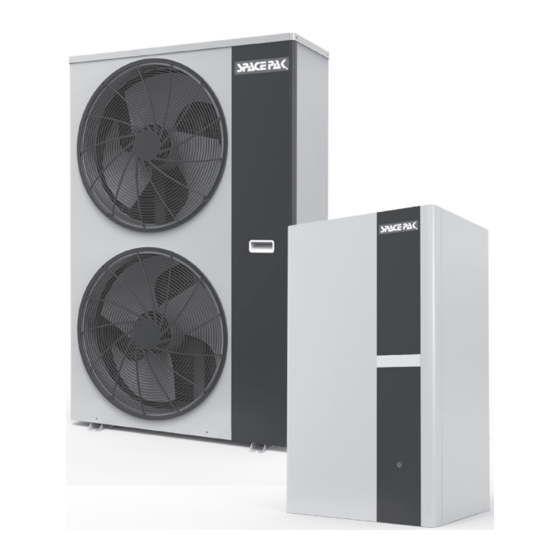
Page 3: Section 2: Unit Specifications
Electrical box Split Inverter Air-to-Water Heat Pump Section 2: Unit Specifications Wire holes 1. Initial Use Model: P10(O) Prior to initial start-up all air must be removed from the hydronic loops, and power should be applied to the unit at least 8 hours Valve cover prior to starting in heating or cooling. This will allow crankcase heater time to boil refrigerant out of compressor oil. Inverter Ultra-Low Temperature Air Source Heat Pump Figure 2.1 Outdoor Unit Electrical components Electrical box behind panel. 54.7" 15.6"... - Page 4 Split Inverter Air-to-Water Heat Pump Unit Specifications Inverter Ultra-Low Temperature Air Source Heat Pump Water Heater Figure 2.2 Indoor Unit 29.5" 17.3" 13.6" Wire holes 1" NPT Water in (Return) 5/8" SAE Flare R410A Connection 3/8" SAE Flare R410A Connection 1" NPT Water Out (Supply) Wall – 4 –...
- Page 5 Split Inverter Air-to-Water Heat Pump Unit Specifications Outdoor Indoor Heating Capacity Range* Btu/Hr 20,473-71,574 Heating Efficiency* Up To 3.09 Heating Capacity Range** Btu/Hr 14,777-47,315 Heating Efficiency** Up to 2.15 Cooling Capacity Range*** Tons 2.5-5.2 Cooling Efficiency*** 12.5 Cooling Efficiency**** IPLV 17.14 Water Temp Range Deg F...
-
Page 6: Section 3: Installation
Split Inverter Air-to-Water Heat Pump Section 3: Installation Choose the Right Heat Pump Unit Electrical Connections Perform appropriate load calculation to determine required Both the SISI indoor module and the SISO outdoor module must heating or cooling load for the project. Refer to specifications in be connected to individual circuits, each sized and protected this manual to determine proper size heat pump. - Page 7 Split Inverter Air-to-Water Heat Pump Water System Table 1 SIS Glycol Concentrations (10% Minimum, 35% Maximum) Propylene Glycol (concentration by volume) Min. temp of burst protection 22°F/-5.6°C 11°F/-11.7°C -1°F/-18.3°C -18°F/-27.8°C -46°F/-43.3°C Capacity Multiplier 0.99 0.98 0.97 0.96 0.94 Pressure Drop Multiplier (Cooling) 1.27 1.34 1.42 Pressure Drop Multiplier (Heating) 1.27 1.34 Minimum Expansion Volume/System Volume Heating and Cooling...
- Page 8 Split Inverter Air-to-Water Heat Pump Glycol / Water Mixture Open the high point purge valve, (not shown in illustration, as If unit is operating in a cooling capacity then the it may be inside the air handler) while slowly filling the system. water system must contain a mixture of inhibited Close the valve when air is removed from the system and water glycol and water with thermal protection sufficient begins to flow out of the valve.
- Page 9 Preparations before Installation Acceptance Split Inverter Air-to-Water Heat Pump Inspection Upon receipt of the goods, the user shall inspect the unit carefully to confirm that no damage has occurred during the transport, that the screws are not loose, and that all spare parts have Preparations Before Installation been received.
- Page 10 Installation Instructions Split Inverter Air-to-Water Heat Pump Unit Installation Unit Installation Clearances The outdoor unit can be installed separately or in multiple. When mulitple outdoor units are When mulitple outdoor units are installed, attention should be paid to their arrangement so as to ensure that the space around the installed, attention should be paid to their arrangement so as to ensure that the space around outdoor units does not affect the installation of return air, air outlet, system piping, and other devices.
- Page 11 If the unit is mounted on the wall, it is necessary t protection measures to prevent icing in winter due to lo may drop and cause injury. Split Inverter Air-to-Water Heat Pump Unit Installation Installation Position - Outdoor Unit Installation Position - Indoor Unit >800 1.
- Page 12 Installation Instructions Split Inverter Air-to-Water Heat Pump Installation Instructions Outdoor Unit Unit Installation The unit is supplied with a damping device, of which the installation method is as follows: Outdoor Unit Unit 1. Ensure the flatness of concrete foundation is within ±3mm and then place the unit Install Vibration Dampeners Device - Outdoor Unit on the cushion block;...
- Page 13 Unit Install Connection Pipe ● fixing; The taper end of the connection pipe is aligned with the conical surface of corresponding valve Split Inverter Air-to-Water Heat Pump install connector; dampin 2. Tighten the connection pip nut firmly with a wrench. Unit Installation g device Install Flare Connections...
- Page 14 Install Connection Pipe Split Inverter Air-to-Water Heat Pump Installation Instructions The maximum length of the pipe is 10 meters. The Unit length can be selected to the customer's needs. And fixing; the unit installation is optional with two solutions: install Unit Installation dampi Install Connection Pipe...
- Page 15 Split Inverter Air-to-Water Heat Pump Refrigerant Charging This section provides details on installation and charging of the refrigeration line set with the unit. Charging Table R410a Charging Table Field refrigerant piping consists of liquid and suction lines from the outdoor unit to the indoor unit coil. Feet Add (oz) <16...
- Page 16 maintenance, service, repair and disposal of appliance. Leak detector must be capable of sensing HFC Approved methods of recovery, recycling or reclaiming refrigerant. must be followed. After completing the leak testing the line set and indoor coil Split Inverter Air-to-Water Heat Pump as outlined in figure 13, proceed to Evacuating Line Set and Indoor Coil on page 17.
- Page 17 Split Inverter Air-to-Water Heat Pump Evacuating Line Set and Indoor Coil Evacuating Line Set and Indoor Coil CONNECT GAUGE SET HIGH NOTE � Remove cores from service valves (if not already done). Connect low side of manifold gauge set with 1/4 SAE in−line tee to vapor line service valve Connect high side of manifold gauge OUTDOOR...
- Page 18 Split Inverter Air-to-Water Heat Pump Danger of Equipment Damage. Avoid deep vacuum operation. Do not use compressors to evacuate a system. Extremely low vacuums can cause internal arcing and compressor failure. Damage caused by deep vacuum operation will void warranty. Evacuating the system of non−condensables is critical for proper operation of the unit. Non−condensables are defined as any gas that will not condense under temperatures and pressures present during operation of an air conditioning system. Non−condensables and water suction combine with refrigerant to produce substances that corrode copper piping and compressor parts.
- Page 19 Split Inverter Air-to-Water Heat Pump Installation Typical System Diagram Figure 3.11 – 19 –...
- Page 20 (4) Connect the power supply properly. Connection of the power supply line must be firm, but it shall not be pulled too tightly. Otherwise, the cable may break or fall off, resulting in fire or other accidents. Split Inverter Air-to-Water Heat Pump (5) Strong and weak electrical wiring should be routed separately and cannot interfere with each other.
- Page 21 开关 Power Split Inverter Air-to-Water Heat Pump cable Electrical Installation Communication cable The RS485 Communication Cable shall be separated from any line voltage conductors. It shall be installed to protect from weather or Model: P10(O) Model: P10(I) fraying during installation. Figure 3.14 Electrical Electrical box...
-
Page 22: Section 4: Wiring
Split Inverter Air-to-Water Heat Pump Section 4: Wiring Figure 4.1 SIS Outdoor Unit AI 01 AI 02 AI 03 AI 04 AI 05 RO 01 AI 06 AI 07 RO 02 AI 08 AI 09 RO 03 AI 10 AI 11 RO 04 AI 12 RO 05... - Page 23 Split Inverter Air-to-Water Heat Pump Wiring Figure 4.2 – 23 –...
- Page 24 Split Inverter Air-to-Water Heat Pump Wiring with SSIC Controller Figure 4.3 – 24 –...
- Page 25 Split Inverter Air-to-Water Heat Pump Wiring Outdoor Unit Main Board I/O Interface Description Label Description Neutral Terminal Line Voltage Terminal R003 4-Way Valve Control Terminal R006 Bottom Coil Heat Tape Terminal R007 Crankcase Heat Tape Terminal R008 Spray Valve Terminal AI03 Discharge temp sensor input AI05 Ambient temp sensor Input AI07...
-
Page 26: Section 5: Control
Split Inverter Air-to-Water Heat Pump Section 5: Control Figure 5.1 Easy touch-screen display panel allows users to change between heating and cooling modes as well as access parameter and faults. – 26 –... - Page 27 Time interface Down Auxiliary Mute key Mode key On/off key Split Inverter Air-to-Water Heat Pump interface Timer icon Control 2.Key and icon function instruction Touch Screen Wire Controller Interface Introduction - Key and Icon Function Instruction 2.1 Key function instruction Key Function Instruction Key symbols Designation...
-
Page 28: Section 6: Operation
Split Inverter Air-to-Water Heat Pump Section 6: Operation Quick Start-up guide The following parameter set points are required. (Heating or cooling mode must be manually selected using the mode button The SIS system can be field commissioned to work in 2 modes, on the indoor unit touch pad and following the menus located in heating/cooling “remote controlled”... - Page 29 Operation Instructions Split Inverter Air-to-Water Heat Pump Operation Special Function Settings Figure 6.3 Query Press “Search” to view water supply, return water, and settings Press “Up” or “Down” arrow to switch what to be viewed, and press “ON/OFF” to exit to the main interface To View Fault Log Electric Heating Four-way Valve...
- Page 30 Split Inverter Air-to-Water Heat Pump Operation Operation Instructions Operation Instructions From the main screen hold search key for 3seconds to enable status inquiry screen. In this screen the display will indicate if compressor, pump, 4way valve, fan, electric heater or defrost are active (see figure 5.5) By pressing up or down keys the user can view values from the table below. Figure 6.4 Status Information Query Status Information Query Item Units Inlet (return) Water T °F N o . N o . Status Status N o .
- Page 31 1.1 When the unit hasn’t been matched room thermostat, the ON/OFF function is Flow symbol When main display area displays flow, it is on. controlled by wire controller. Flow symbol When main display area displays flow, it is on. When the unit is off, press‘ ’key for 1 second to start it up.
- Page 32 State of defrosting Heating mode Split Inverter Air-to-Water Heat Pump During defrosting, mode switch can be performed. The new mode will takes effect when defrosting is completed. Operation 3. Temperature setting On the main interface, short press ‘Up’ or ‘Down’ key, it will enter temperature setting 3.
- Page 33 2) On the query parameter interface, it is not allowed to automatically return to the main 1) On the main interface, short press ‘M’ key to enter the parameter query interface. interface. It need to short press the “ON/OFF” key to return. 2) On the query parameter interface, it is not allowed to automatically return to the main Split Inverter Air-to-Water Heat Pump interface.
- Page 34 Split Inverter Air-to-Water Heat Pump Operation 5. Factory Settings From the home screen: To adjust or view factory settings, press the "search" key once for 3 seconds, then again for another 3 seconds to enter the Password screen. The password screen will display "000". Use the up or down arrows to enter password "066". Press the "M" key to accept the password. The parameter list will begin with Section "A". Use the up or down keys to access the appropriate section based on the chart below. Once the appropriate section is found, press the "M" key to access that sections parameter. For example: If contractor would like to change the temp set-point in heating; Use the up and down to keys to enter a password of "066", press "M" to save the password, then use the up or down keys to locate the section of "R" parameters and press "M". Once selected scroll to "R02" and press "M" again to access the heating temp set-point parameter. Once the parameter has been adjusted, the contractor will press "M" to save. If "M" is not pressed, parameter change will not be saved.
- Page 35 Split Inverter Air-to-Water Heat Pump Operation Parameter List Section Code Description Units Range Default Notes EVI Operation 0 to 3 0 = EVI Inactive, 1 = EVI in Cooling, 2 = EVI in Heating, 3 = Both Running Mode Manufacturer setting, do not alter Auxiliary Electic Heater 0 = No Aux Heater, 1 = Aux heater installed and active Heat Pump Mode...
- Page 36 Compressor Split Inverter Air-to-Water Heat Pump Pump Compressor Pump Operation 6. Error Screen 1) When a fault has occurred, the most recent fault will be displayed and should have a "01" as the most recent fault. 2) If other faults have occurred press the "up" or "down" keys to display each error. Refer to the fault codes chart for details on each possible error and solution. 9.
- Page 37 Split Inverter Air-to-Water Heat Pump Operation Auxiliary Electric Heater Operation When parameter H03 is set to 1, the electric heater function is enabled. The heater will energize when all (5) of the below conditions are met. 1. The flow switch has been closed for a minimum of 1 minute. 2. The heater overtemp switch is closed. 3.
-
Page 38: Section 7: Maintenance/Troubleshooting
Split Inverter Air-to-Water Heat Pump Section 7: Maintenance/Troubleshooting All repairs and troubleshooting should be performed by a qualified/licensed technician. Repairs/troubleshooting improperly can void the product warranty and could result in injury, death or premature failure of the product. Please contact Mestek technical support for any issues not covered in the following tables. Repair Condition Possible Cause Solution Reduced heating capacity Excessively frosted Coil Ensure Defrost function is enabled and adjusted for local condtions. - Page 39 Split Inverter Air-to-Water Heat Pump Maintenance/Troubleshooting Faults Query Corresponding Display Fault Cause Troubleshooting Corrective Action Status Display Return Water Temp Failed or Disconnected Check wiring, check sensor for Repair wiring or replace sensor Sensor Fault Sensor open or shorted condition Supply Water Temp Failed or Disconnected Check wiring, check sensor for Repair wiring or replace sensor Sensor Fault...
- Page 40 Split Inverter Air-to-Water Heat Pump Maintenance/Troubleshooting Faults Query Corresponding Display Fault Cause Troubleshooting Corrective Action Status Display IPM Overcurrent Electronic control fault Contact Technical Support Adjust or replace faulty control protectuon component IPM Overtemp Electronic control fault Contact Technical Support Adjust or replace faulty control protectuon component Radiator Temp...
- Page 41 Split Inverter Air-to-Water Heat Pump Maintenance/Troubleshooting Replacement Parts Part No Description Indoor Outdoor 45W41-WG1300-01 PANEL, GLASS FRONT 45W11-WG1301-01 OVERLAY, TOUCHSCREEN 45W09-WG1302-01 DISPLAY, TOUCHSCREEN 45W40-WG1303-01 ADAPTER, SAE FLARE, -10 45W40-WG1304-01 ADAPTER, SAE FLARE, -06 45W11-WG1305-01 FLOW SWITCH 45W41-WG1306-01 MOUNTING PANEL, REAR 45W41-WG1307-01 SHELL, ENCLOSURE 45W50-WG1308-01 HEAT EXCHANGER, TUBE IN SHELL 45W41-WG1309-01 PANEL, BOTTOM 45W41-WG1310-01 DOOR, FRONT ACCESS 45W09-WG1311-01...
- Page 42 Split Inverter Air-to-Water Heat Pump Limited Warranty SpacePak “Solstice Inverter”* Series Air to Water Heat Pumps Subject to the terms and conditions of this Limited Warranty Statement (the “Limited Warranty”), SpacePak warrants to the original purchaser of the “Solstice Inverter” Series (as used herein, “System”...
- Page 43 Split Inverter Air-to-Water Heat Pump – 43 –...
- Page 44 IN UNITED STATES: 260 NORTH ELM ST. WESTFIELD, MA 01085 800-465-8558 IN CANADA: 7555 TRANMERE DRIVE, MISSISSAUGA, ONTARIO, L5S 1L4 (905) 670-5888...
Need help?
Do you have a question about the SIS Series and is the answer not in the manual?
Questions and answers