Table of Contents
Advertisement
Contents
2.2. Display Description
3.3.1 TX
4
4
4
6
8
8
8
9
10
11
11
12
12
13
14
14
16
22
22
22
23
23
2 3
2 3
23
23
23
2 3
23
1
3 . 3 . 4 G ai n C o n t r o l
3 . 3 . 5 R a i n / S n o w R e m o v a l
3 . 3 . 6
T o o p e r a t e t h e a l e r t f u n t i o n
3.3.8 To remove the Radar Interference
3.3.9 To elemina③e ③he Ship ② Heading Line
3.3.18 To measure the time to the target
3 . 3 . 1 9 T o d i s p l a y t h e W a y p o i n t ... ...
3 . 3 . 2 0 T o d i ② p l a y ③ h e o ③ h e ① ② h i p ② ③ ① a c k l i n e
2
2 3
2 5
2 6
28
28
29
29
29
29
30
31
34
34
34
35
3 5
3 6
36
38
39
39
39
40
41
41
41
42
43
45
45
45
45
45
Advertisement
Table of Contents

Related Manuals for Samyung ENC SMR-7200

Summary of Contents for Samyung ENC SMR-7200
-
Page 1: Table Of Contents
3.3.14 To change the way of direction symbol 1.5.2 Antenna (RSU-7200) 3.3.15 To change the way of bearing display 1.5.3 Display Unit (SMR-7200) 3.3.16 To change the way of displaying bearing ine/cursor 1.5.4 Connection Cable 3.3.17 To compensate the magnetic 3.3.18 To measure the time to the target... -
Page 2: Chapter 1. Overview
: 72NM 6.1.3 Check the cabling Display Unit 6.2 Antenna SMR-7200 monitor is designed to receive the input signal from Antenna and 6.2.1 OpenArray to display at the optimum conditions on the TFT LCD screen, based on the 6.2.2 Bracket SAMYUNG ②... -
Page 3: Construction
1.4 Construction Components Description Samyung CODE Remark Manual SMR-7200-ME RSU-7200-15M ANTENNA-DISPLAY CABLE ACC-CAB-010 POWER CABLE STR-595 SURGE CABLE 1 2 0 0 [Pic. 1.1] RSU-7200 External Diagram... -
Page 4: Specifications
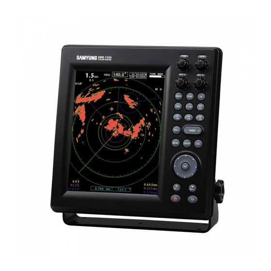
SCANNER Plane of Polarization : Horizonal Target Wave Polar Pattern 1) Horizontal Beam Width: 2.0° [Pic.1.2] SMR-7200 External diagram of Display 2) Ve①③ical Beam Wid③h섭 25° 3) Side Lobe Level : Below -21dB Revolution : Approx. 24 R/Min ... -
Page 5: Display Unit (Smr-7200)
: Switch 0.9 sec / 600Hz - 12, 24, 36, 48, 64, 72NM 19) Enter : Switch 20) Direction Button (8 Directions) : Switch 1.5.3. Display Unit (SMR-7200) 21) Brightness : Switch Dimensions 23) Power : Switch 1) Width... -
Page 6: Chapter 2. How To Operate Panel And Menu
Chapter 2. How to operate panel and menu 2.1.2 Directional Key 2.1 Front Panel Buttons and Knob They are used to move the cursor, turn the EBL, change the VRM size and move You may adjust the various data on the screen by using the the control keys as to any of the sub-menu. -
Page 7: Display Description
2.2 Display Description 2.3 Menu Functions In addition to the functions used by the front panel keys, SMR-7200 has the functions controllable from menu.. 2.3.1 Menu Composition You may change the language to Korean, English and others. Press MENU and select any wishful setup menu by using direction button. -
Page 8: Menu Functions
2.3.2 Menu fucntions 2.3.2.1 Echo Settings • Target track This function is to track target and will display the target during set value of RPM and will change colour at different levels leaving target s trail This function will operate by pressing TRAIL. RPM may be adjusted from Off to 4. - Page 9 2.3.2.2 AIS Setting 2.3.2.3 Display setting • Display May decide to display AIS or not. • Colors Selecting a color of AIS target; you may choose Green, Red, Blue, White, or Black. • Mode This menu allows to display bow, N-UP, C-UP and True Motion. Bow mode only available when there is no external •...
- Page 10 • Sector Blank • FULL SCREEN You may set Sector Blank in the radius 360˚ by 1 degree. Target display gets displayed as FULL SCREEN It will be displayed with blue broken lines. • Compass You may turn on/off the compass function in the screen. •...
- Page 11 2.3.2.4 Communication setting 2.3.2.5 System setting • NMEA0183-Port This is a menu to set NMEA0183 port, you may check the transmission speed and communication status. It provides Communication speed at 4800, 9600 and 38400. Unit will display the communication status coming from the external equipment.
-
Page 12: Chapter 3. How To Operate The Unit
• STC Curve The following drawings show the curve between Distance to Gain Chapter 3. How to operate the unit shown as the following drawings. 3.1 General Idea 3.1.1 Power input and Operation 1. Power input To power on, press POWER button. ... -
Page 13: Image Control
3.1.3 Image control 3.3.2.1 STC Curve the volume of the tuning/gain of (sea clutter), The following drawings show the curve between Distance to Gain (rain/snow), removal to display the optimum image. shown as the following drawings. 3.1.4 Power off 1. Stop transmission (TX). ... - Page 14 3.3.5 In order to remove the interference of rain/snow 3.3.4 Gain control ATTENTION ATTENTION ※ It should be always observed by adjusting the optimum conditions. ※ Too much adjustment of rain/snow removal will restrain the target of shipsor ※ If the gain is too low, the targets may not be displayed. hazards as well as any images by rain/snow.
- Page 15 3.3.7 To operate the alert function 3.3.6 To remove the interference of Sea Level Wave caused by the Sea Wave the guard zone in order to use the alert. Guard Zone means [Zone] to be set on PPI screen ATTENTION ※...
-
Page 16: To Eliminate/Display The Scale Of Range Ring
3.3.8 To eliminate/display the scale of Range Ring 3.3.10 To change the color of the ship s heading line. 1. Press the Range Ring Key 1. Press the ship s heading line key The brightness of ON/OFF will be adjusted. ... -
Page 17: To Change Distance Unit
3. Measurement of the distance and bearing by using F EBL/VRM 3.3.15 To change the way of direction symbol Press the F EBL/VRM key. 1. Indication of ship s head line (H-UP) EBL/VRM will appear on the radar screen. Menu ... - Page 18 2. Indication of North direction 3. Indication of course-up (C-UP) Menu View Mode Input North Input Esc Menu View Mode Input Course Input Esc The vertical line will indicate the direction of the North, the line to 10 degree ...
-
Page 19: To Change The Way Of Bearing Display
3.3.16 To change the way of bearing display 3.3.19 To display the trace of the target. 1. True Bearing Menu System Bearing Display Input True Bearing Input Esc It may ascertain the other ship s movement in track line distance and ... -
Page 20: Connection To The External Navigation Equipment
3.3.21 To change the color of the radar screen and ECHO image. SMR-7200 GPS PLOT UNIT 1. Configuration of the color of ECHO image and background. HDT_OUTPUT Menu Echo Color Selection Input Choose the color Input Esc... -
Page 21: Chapter 4. Screen View
4.2 Reflection from the target Chapter 4. Screen view The strength of reflection from the target is related to not only the size of the target 4.1 The distance from the target to the height of target but the shape and the materials composed of it. Therefore the strength of reflection is not considered to be relative to the size of the target. -
Page 22: False Image
4.3.2 False Image Chapter 5. Installation There is a possibility that non-existing targets may be shown or any existing ③a①ge③② may no③ be ②hown ③h①o④gh ③he image. Thi② image i② called vi①③④al image . What mainly causes such false image as follows; CAUTION 1. -
Page 23: How To Install Antenna
5.2.3 Connection to Equipment Cable 5.2.2 How to install Antenna 1. Antenna (RSU-7200) 1. Take a caution when antenna is installed on High Speed Vessel Generally the head of High Speed Vessel will be up float when ship is in full speed. Due to this, in case the Antenna being installed in even level and trim (angle of ②hip ②... -
Page 24: Display Set-Up
5.3. DISPLAY SET-UP 5.3.1. Location for installation ATTENTION ※ A display must be installed 1 meter away from a magnet compass. ※ It may be harmful to the magnet compass in case of closer installation. Select the location for easy-investigation and maintenance. 5.3.2 How to Install (1) Install the display according to the Block Diagram. -
Page 25: Initial Installation
5.6. Initial Installation In case of the first time, it must be executed an initial adjustment. ATTENTION 5.6.1 Initial Installation ※ The initial-setting should be executed in transmitting condition. Following is how to go to Initial setup menu ※ Wi③ho④③ ③he ini③ial ②e③③ing, ③he ③a①ge③ ma①k, di②③ance and di①ec③ion may be w①ong. Menu ... -
Page 26: Tune Adj
5.6.6 Tune ADJ ATTENTION On the front, there is key control knob for Tunning and may be adjusted by 64 Device came out with fully adjusted. For resetting for default basic different levels. manufacture is limited to end-users. Not recomannding for adjusted by For setting procudre, make Tune VR to the center and set target object and end-users all the time. -
Page 27: Chapter 6. Maintenance
CAUTION Chapter 6. Maintenance ※ Don ③ ④②e Benzene, Ga②oline, T①ic①ene, Keltone and any solvents other than alcohol. 6.1. General Maintenance Check periodically the tightness of the attached bolts. (1) A regular maintenance is required for the radar to perform in a good order. (2) The unexpected troubles would be less by paying proper attention to timely maintenance. -
Page 28: Chapter 7. Installation Drawing And Circuit Diagram
Chapter 7. Installation drawing and circuit diagram [Antenna Unit(RSU-7200)]... - Page 29 RSU-7200 Antenna CODE NO. RSU-7200 SAMYUNG Ø11 X 16C Antenna SRCN2A 25-16P CODE NO RSU-7200-15M Cable L=15m CVV-SB2.0 SQ X 2C Power SCN20- CODE NO. ACC-CAB-010 Cable L=3m KIV 5.5mm 7 Ground Cable L=3m [Display Unit(SMR-7200)] CODE NO. STR -595...
- Page 30 Ø4 X 16 Chapter 8 Warranty Information Stainless Thank you for purchasing Samyung ENC LTD’s SMR-7200. This manual includes the proper Piece CODE NO. SPR-1407 way of operating and installing the unit and warnings. Please keep this manual in a safe place.
Need help?
Do you have a question about the SMR-7200 and is the answer not in the manual?
Questions and answers