Table of Contents
Advertisement
Quick Links
Operation & Installation Instructions
LTW-4
Series
System
LTW-402
LTW-502
LTW-602
LTW-403
LTW-503
LTW-603
LTW-406
LTW-506
LTW-606
LTW-410
LTW-510
LTW-610
LTW-415
LTW-515
LTW-615
LTW-420
LTW-520
LTW-620
LTW-H4
Series
LIGHTWAVE - Standard Systems
Rated Flow
2 gpm
3 gpm
6 gpm
11 gpm
15 gpm
21 gpm
LTW-5 Series
LTW-6 Series
System
Rated Flow
LTW-H405
LTW-H505
5 gpm
LTW-H605
LTW-H410
LTW-H510
10 gpm
LTW-H610
LTW-H415
LTW-H515
15 gpm
LTW-H615
LTW-H425
LTW-H525
25 gpm
LTW-H625
LTW-H440
LTW-H540
40 gpm
LTW-H640
LTW-H5 Series
LTW-H6 Series
Advertisement
Table of Contents

Subscribe to Our Youtube Channel
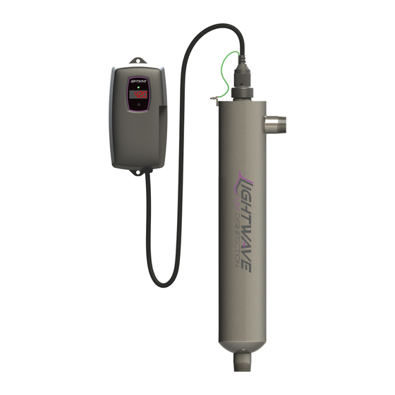
Summary of Contents for Lightwave LTW-4 Series
- Page 1 Operation & Installation Instructions LTW-4 LTW-H4 LTW-5 Series LTW-H5 Series Series Series LTW-6 Series LTW-H6 Series LIGHTWAVE - Standard Systems System Rated Flow System Rated Flow LTW-402 LTW-H405 LTW-502 2 gpm LTW-H505 5 gpm LTW-602 LTW-H605 LTW-403 LTW-H410 LTW-503 LTW-H510...
- Page 2 This is chemical free process which is simple in its concept and effective in its abilities to inactivate microorganisms present in the water supply. Simple maintenance, continuous disinfection and ultimately safe water, LIGHTWAVE makes it that easy. P a g e...
-
Page 3: Table Of Contents
TABLE OF CONTENTS Safety Considerations ......................4 Before You Begin ........................ 4 Water Quality Parameters ....................5 Assembly ..........................6 System Sizing ........................8 Location ..........................8 Installation ......................... 9 System Disinfection ......................12 Cleaning the Quartz Sleeve ....................12 Cleaning the UV Sensor .................... -
Page 4: Safety Considerations
Safety Considerations Although your UV system has been manufactured to the highest safety standards, care must be followed when operating and/or maintaining your system. 1. Before servicing this equipment, disconnect the power cord from the electrical outlet. 2. Energy given off by the UV lamp is harmful to your eyes and skin. NEVER look directly at an illuminated UV lamp without adequate eye protection and always protect your skin from direct exposure to the UV light. -
Page 5: Water Quality Parameters
<0.1 ppm (0.1 mg/L) UVT (transmittance): >85% (Please contact LIGHTWAVE if water has a UVT that is less than 80% for pre-treatment recommendations) You can have your water tested at a private analytical laboratory or by your local dealer. It is always recommended to install pre-filtration of at least 5 microns prior to a UV disinfection system. -
Page 6: Assembly
Assembly Unpack the system and ensure all the components are included with the system. Your system is shipped with the following components: STANDARD OUTPUT LAMP SYSTEMS LAMP GLAND NUT CONTROLLER LTW-320006 4.1 SYSTEMS LTW-RCB401 O-RING 5.1/6.1 SYSTEMS LTW-300038 LTW-RCB5601 UV LAMP LTW-RL210 “-02”... - Page 7 HIGH OUTPUT LAMP SYSTEMS LAMP GLAND NUT LTW-320006 CONTROLLER O-RING 4.1 SYSTEMS LTW-300038 LTW-RCHO412 5.1/6.1 SYSTEMS LTW-RCHO5612 UV LAMP LTW-RL210HO “-05” series LTW-RL330HO “-10” series CLAMPS LTW-RL420HO “-15” series LTW-RL600HO “-25” series LTW-RL950HO “-40” series SLEEVE SPRING 310039 GLOW PLUG QUARTZ SLEEVE LTW-300016 Complete Assembly LTW-QS210 “-05”...
-
Page 8: System Sizing
(See Figure 1). For Point of Use (POU) systems, install the unit just before the faucet. LIGHTWAVE recommends that a 5 micron filter be installed before the UV system for a final polishing step before the water is disinfected. -
Page 9: Installation
To facilitate lamp removal, ensure there is enough space at the lamp connector end to safely remove the UV lamp and/or quartz sleeve (See Figure 2). The controller will require a ground fault circuit interrupter (GFCI or GFI) outlet and should be mounted beside or above the reactor. PLEASE NOTE: All UV disinfection systems are intended for indoor use only as they should not be exposed to the elements. - Page 10 Step 6: Once the system has been plumbed in, gently remove the quartz sleeve from its packaging being careful not to touch the length with your hands. The use of cotton gloves is recommended for this pro- cedure as oils from the hands can leave residue on the sleeve and lamp which can ultimately block the UV light from getting to the water.
- Page 11 Step 11: Always hold UV lamps by their ceramic ends, not by the lamp quartz. Remove the lamp from its packaging. Again, the use of cotton gloves is recommended. Remove the lamp key from the lamp’s connector and set it aside for the next step. Be careful to not touch the key’s exposed contacts.
-
Page 12: System Disinfection
System Disinfection With a new installation, or any time the UV system is shut down for service, without power, or is inoperative for any other reason, the lines in the home or facility could be contaminated. Use the following steps to fully disinfect the lines throughout the entire home or facility. Step 1: Check for and remove any “dead ends”... -
Page 13: Cleaning The Uv Sensor
Step 10: Dry the sleeve with separate cloth. Step 11: Replace the o-ring and slide the sleeve back into the reactor following steps 7 and 8 from the installation section of the manual. Cleaning the UV Sensor Depending on the water quality, the UV sensor may require periodic cleaning. At a minimum, the UV sensor should be cleaned on an annual basis. -
Page 14: Ltw-4 Controllers
When the UV lamp is not on or the lamp life has expired, the LED will be illuminated red and an audible buzzer will be sounding. To remedy this condition, the UV lamp must be replaced with a new genuine LIGHTWAVE UV lamp. LTW-H4 LTW-4... -
Page 15: Ltw-5 Operational Screens
A final module screen is displayed showing which specific modules were initialized. The controller then displays the lamp optimization screen for 60 seconds to allow the lamp to reach its optimum output. Finally, a final “start-up complete” screen is displayed. The system will now be ready to disinfect water flow. -
Page 16: Lamp Countdown Sequence
audible chirp every audible chirp every constant audible cycles with red low 15 seconds 15 seconds alarm UV screen Lamp Countdown Sequence The system counts down the number of days until a lamp change is required. LTW-5 LTW-6 LTW-4 At thirty days remaining, the LED or display screen will change to a yellow caution indicator. At seven days remaining, the system will additionally repeat an audible chirp. -
Page 17: System Service Suggested
A QR code (Quick Response code) is a matrix barcode first designed for the automotive industry. LIGHTWAVE uses the QR code to store a link to a specific page on our website. Users with a camera phone equipped with the correct reader application can scan the image of the QR code and over a wireless network connect to a LIGHTWAVE web page in the phone’s browser. -
Page 18: System Troubleshooting
System Troubleshooting Hard Alarms: The following give a constant audible alarm. If present, the solenoid valve is closed, and the 4-20, remote alarm and WiFi modules transmit the alarm. System Display Problem Resolution Reset lamp protection circuit -unplug unit for 10 seconds. The system has detected Replace the lamp with the a problem with the... - Page 19 Warning: After any hard alarm, the home or facility should be disinfected. Follow the steps under the “System Disinfection” heading. Boil Water Advisory: If any failure occurs on a LIGHTWAVE UV system, the water must not be used for human consumption until the system is returned to a safe operational mode.
-
Page 20: Temperature Management Devices
Temperature Management Devices Your LIGHTWAVE UV system is designed to run continuously to ensure optimal disinfection. However, during periods when no water is drawn through the system, the energy from the disinfection process can cause the temperature of the water inside the chamber to rise. In extreme situations elevated water temperature or the fluctuation in temperature can lower the output of the UV lamp. - Page 21 REMOTE ALARM CONNECTION MODULE: Allows for a connection to a remote device such as a buzzer, light, alarm system, PLC, etc., via a pair of contacts. In normal operation the OK and COM contacts will be connected, and in a fault condition (Low UV, Lamp fail, Power Fail), the Fault and COM contacts will be connected.
-
Page 22: Standard Output System Specifications
Standard Output System Specifications EQUIPMENT SPECIFICATIONS Residential systems (standard output lamps) Multi-Use / LTW-402 LTW-403 LTW-406 LTW-410 LTW-415 LTW-420 MODEL LTW-502 LTW-503 LTW-506 LTW-510 LTW-515 LTW-520 LTW-602 LTW-603 LTW-606 LTW-610 LTW-615 LTW-620 2.0 gpm 3 gpm 6 gpm 11 gpm 15 gpm 21 gpm Flow Rate... -
Page 23: High Output System Specifications
High Output System Specifications EQUIPMENT SPECIFICATIONS Residential Crossover systems (high output lamps) LTW-H405 LTW-H410 LTW-H415 LTW-H425 LTW-H440 MODEL LTW-H505 LTW-H510 LTW-H515 LTW-H525 LTW-H540 LTW-H605 LTW-H610 LTW-H615 LTW-H625 LTW-H640 5.0 gpm 10 gpm 15 gpm 25 gpm 40 gpm Flow Rate 18.91 lpm 37.9 lpm 57 lpm... -
Page 24: Limited Warranty Statement
LIGHTWAVE will not be liable for any costs of removal, installation, transportation, or any other charges which may arise in connection with a warranty claim. LIGHTWAVE will not be liable for damage or wear to products caused by abnormal operating conditions, accident, abuse, misuse, unauthorized alteration or repair, or if the product was not installed in accordance with the Manufacturers printed installation and operating instructions. -
Page 25: Warranty Registration
• Product is installed outdoors in direct contact with the environment (rain). • Product is installed in freezing temperatures. • Product is used in conditions that exceed LIGHTWAVE’s specifications. TO GET WARRANTY SERVICE Please contact the Dealer or Distributor where the product was originally purchased to obtain service under this warranty. - Page 26 2 6 | P a g e...
- Page 27 2 7 | P a g e...
- Page 28 Van Isle Water 461 Dupplin Rd Victoria, BC V8Z 1B8 250-383-7145 vanislewater.com PN#910415 Version Date: 12-2020...
Need help?
Do you have a question about the LTW-4 Series and is the answer not in the manual?
Questions and answers