Table of Contents
Advertisement
Quick Links
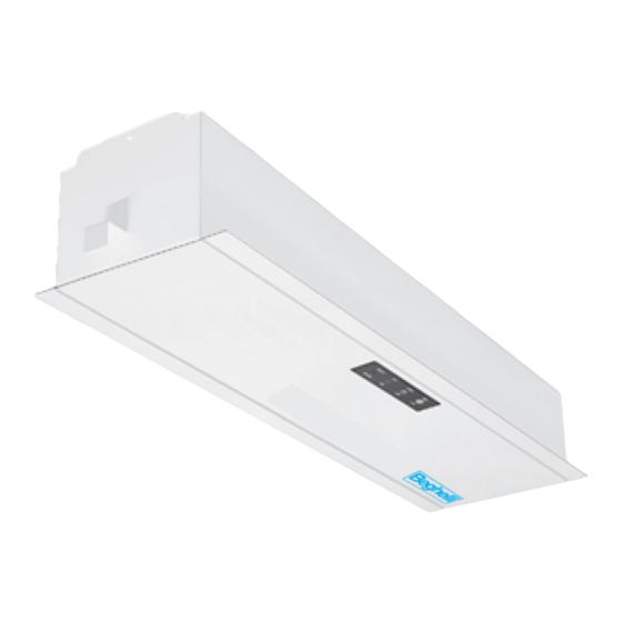
Installation And Operation Instructions Vesta-M Micro
Micro-Inverter Power Systems
Lead Calcium Battery Models: VST-M-32 and VST-M-55
Nickel Cadmium Battery Models: VST-M-20 and VST-M-35
Surface (-S), Recessed (-R) and Ceiling T-Grid (-T) Mounted versions
Beghelli USA • 3250 Corporate Way • Miramar, FL 33025 • TEL: 954-442-6600 • FAX: 954-442-6677
Advertisement
Table of Contents

Related Manuals for Beghelli Vesta-M Micro


Summary of Contents for Beghelli Vesta-M Micro
- Page 1 Lead Calcium Battery Models: VST-M-32 and VST-M-55 Nickel Cadmium Battery Models: VST-M-20 and VST-M-35 Surface (-S), Recessed (-R) and Ceiling T-Grid (-T) Mounted versions Beghelli USA • 3250 Corporate Way • Miramar, FL 33025 • TEL: 954-442-6600 • FAX: 954-442-6677...
- Page 2 Servicing of this equipment should be performed by qualified service personnel. SAVE THESE IMPORTANT SAFETY INSTRUCTIONS The installation and use of this product must comply with all national, federal, state, municipal, or local codes that apply. Please read this manual thoroughly before operating the Vesta-M micro inverter system.
-
Page 3: Table Of Contents
TABLE OF CONTENTS Description Section 100 System installation instruction Specifications ..............................101. Receiving, Moving, and Storing Systems and Batteries ................ 102. Shipping Damage............................... 102.1 Temporary Storage of Units and Batteries......................102.2 Installation Requirements ..........................103. Operating Environment ............................103.1 High Altitude Operation ............................103.2 Cabinet Mounting ............................... -
Page 4: System Installation Instruction
SECTION 100 SYSTEM INSTALLATION INSTRUCTION 101. Specifications Input • Input voltage: Universal 120 or 277Vac. • Input frequency: 60HZ ±2%. • Input surge protection: Meets UL 924 Output • Output voltage: Universal 120 or 277Vac, 60HZ. Other voltages available upon request •... - Page 5 TABLE 1 (PHYSICAL SPECIFICATIONS) SYSTEM SYSTEM HOUSING HOUSING DIMENSIONS NUMBER OF HOUSING WEGHT* MODEL MOUNTING INSTALLED SIZE STYLE BATTERIES (LBS.) (KG.) LENGTH HEIGHT DEPTH NUMBER VST-M-32-S Surface Small ” (37.5 cm) 7 ” (18.7 cm) 3 ” (7.9 cm) VST-M-55-S Surface Large ”...
-
Page 6: Receiving, Moving, And Storing Systems And Batteries
Storage Temperature: Store all batteries at 0° to +40° C (32° to +104° F). Batteries will have a longer shelf life if stored at 15° C (60° F). The Vesta-M micro electronics and battery cabinets may be stored at -20° to +60° C (-4° to +140° F). -
Page 7: 103.2 High Altitude Operation
The air around the unit must be clean, dust-free, and free of corrosive chemicals or other contaminants. Do not place the Vesta-M micro inverter system or batteries in a sealed room or container. CAUTION: Never Install Batteries in A Sealed Room Or Enclosure 103.2 High Altitude Operation:... -
Page 8: Mounting Hardware
104.2 Mounting Hardware Mounting hardware is not provided. Care should be taken when selecting mounting hardware to as sure that it is the proper type for the application and sized to safely support the systems full weight when installed assuring safe and secure attachment of system to wall surface or building structures. - Page 9 104.5 Recessed Mount (-R) Models: 1) Remove cover and any packing material inside unit housing that may have been used for shipping purposes. 2) Remove the appropriate knockouts, 7/8” diameter, on the top and/or right hand side of the unit housing to facilitate conduit attachment. Also remove the appropriate round knockouts, 5/16”...
-
Page 10: Ac Connections
TEST BEFORE TOUCHING! E) To reduce the risk of fire or electric shock install the Vesta-M micro inverter system and the batteries in at temperature controlled and humidity-controlled indoor area free of conductive contaminants. See Section 103 for operating environment specifications. -
Page 11: 105.2 Ac Input Voltage Selector Plug Installation
105.2 AC Input Voltage Selector Plug Installation Vesta-M micro inverter system may be operated from either 120V or 277V power sources. Determine the actual AC input line voltage and install the provided Voltage Selector Plug in the position next to the system terminal block that matches the line voltage potential as shown in the illustration below CAUTION: Failure to install the Voltage Selector Plug will prevent system operation. -
Page 12: Battery Information
Remove rings and metal wristwatches or other metal objects and jewelry. Don’t carry metal objects in pockets where the objects can fall onto the batteries or into the Vesta-M micro inverter system. -
Page 13: 106.3 Battery Voltage Check
108. System Start-Up Procedure IMPORTANT: The Vesta-M Micro inverter system is a sophisticated electronic backup power supply. Care must be taken to follow the steps below in their exact sequence. Failure to do so may result in possible equipment failure. -
Page 14: 200.1 Safe Shut Down Procedure
90 minutes once a year. We strongly recommend these guidelines be followed to insure system readiness, and to prolong battery life. The Vesta-M micro inverter system was designed with a front panel test switch to facilitate monthly testing. Simply depress the button and hold to test the inverter at anytime. Once released, the Vesta-M will revert back to standby operation. -
Page 15: 200.4 Routine Battery Inspection And Maintenance
Substituting batteries not supplied by the Manufacturer will void the UL listing of the system and may cause equipment failure. To ensure the superior performance of your Vesta-M micro inverter system and to maintain proper charger operation, replace spent batteries only with those having the same part number, voltage and ampere-hour rating as the original batteries.
Need help?
Do you have a question about the Vesta-M Micro and is the answer not in the manual?
Questions and answers