Table of Contents
Advertisement
Quick Links
S H A R I =
SPECIFICATIONS . . . . . . . . . . . . . . . . . . . . . . . . . . . . . . . . . . . . . . . . . . . . . . .
NAMESOFPARTS
VOLTAGE SELECTION . . . . . . . . . . . . . . . . . . . . . . . . . . . . . . . . . . . . . . . . . . .
STRINGING OF DIAL CORD . . . . . . . . . . . . . . . . . . . . . . . . . . . . . . . . . . . . . . .
DISASSEMBLY . . . . . . . . . . . . . . . . . . . . . . . . . . . . . . . . . . . . . . . . . . . . . . . . .
BLOCKDIAGRAM
TEST TAPES FOR MEASUREMENT . . . . . . . . . . . . . . . . . . . . . . . . . . . . . . . . . .
MECHANICAL ADJUSTMENT . . . . . . . . . . . . . . . . . . . . . . . . . . . . . . . . . . . . . .
ACPOWERSUPPLYCORD . . . . . . . . . . . . . . . . . . . . . . . . . . . . . . . . . . . . . . . . .
NOTES ON SCHEMATIC DIAGRAM
SCHEMATIC DIAGRAM . . . . . . . . . . . . . . . . . . . . . . . . . . . . . . . . . . . . . . . .
REPLACEMENT PARTS LIST . . . . . . . . . . . . . . . . . . . . . . . . . . . . . . . . . . . .
GENERAL
Power source:
AC 110 - 127V and 220 - 240V
DC 9 V (UM/SUM-1 or R20 type x 6)
Output power:
PMPO; 15 W
MPO; 8 W
RMS; 4.6 W
Semiconductors:
8 ICs
3 Transistors
13 Diodes
6 LEDs
Dimensions:
W idth; 550 mm (21-5/8" )
Height; 220 mm (8-5/8" )
Depth;
Weight:
3.6 kg (7.9 Ibs.) without batteries
All manuals and user guides at all-guides.com
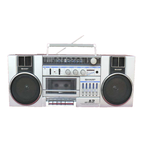
Photo: G F-APZ(S)
. . . . . . . . . . . . . . . . . . . . . . . . . . . . . . . . . . . . . . . . . . . . . .
. . . . . . . . . . . . . . . . . . . . . . . . . . . . . . . . . . . . . . . . . . . . . .
. . . . . . . . . . . . . . . . . . . . . . . . . . . . . . . . . . . . . . . .
. . . . . . . . . . . . . . . . . . . . . . . . . . . . . . . . . .
. . . . . . . . . . . . . . . . . . . . . . . . . . . . . . . . . . .
. . . . . . . . . . . . . . . . . . . . . . . . . . . . . . . . . . . . . . . . . .
(7.5 w + 7.5 W)
(AC operation)
(AC operation)
(2.3 W + 2.3 W)
(DC operation
130 mm (5-I /8" )
SHARP CORPORATION
In the interests of usersafety the set should be restored to its
original condition and only parts identical to those specified be
used.
TAPE RECORDER
Tape:
Compact cassette tape
Frequency range:
80 Hz - 10,000 Hz
Signal/noise ratio:
36 dB
Wow and flutter:
0.15 % (WRMS)
Input impedance:
External mic: 600 ohms
Loaded impedance:
Headphones;
8 - 25 ohms
External speakers;
3.2 - 8 ohms
RADIO
Frequency range:
FM; 87.6 MHz - 108 MHz
AM; 526.5 kHz - 1606.5 kHz
SW,; 7.3 MHz - 22 MHz
SPEAKER
Speakers:
12 cm (4-3/4" ) woofer x 2
Horn type tweeter x 2
Impedance:
3.2 ohms
Specifications for this model are subject to change without
prior notice.
Page
1
2
2
2
3
4
5
5
5 - 7
7
8
15-18
Advertisement
Table of Contents

Related Manuals for Sharp GF-A2Z(S)


Summary of Contents for Sharp GF-A2Z(S)
- Page 1 W idth; 550 mm (21-5/8” ) Height; 220 mm (8-5/8” ) Impedance: 3.2 ohms Depth; 130 mm (5-I /8” ) Weight: 3.6 kg (7.9 Ibs.) without batteries Specifications for this model are subject to change without prior notice. SHARP CORPORATION...
-
Page 2: Names Of Parts
All manuals and user guides at all-guides.com FOR A COMPLETE DESCRIPTION OF THE OPERATION OF THIS UNIT, PLEASE REFER TO THE OPERATION MANUAL. 1234 7 8 9 1011 1. Built-in Microphone 2. Band Selector Switch Stereo Indicator 4. Function Selector Switch 5. - Page 3 All manuals and user guides at all-guides.com Caution on Disassembly Follow the below-mentioned notes when disassembling the unit and reassembling it, to keep its safety and excellent performance: 1. Take cassette tape out of the unit. 2. Be sure to remove the power supply plug from the wall outlet before starting to disassemble the unit and remove the batteries from the unit.
- Page 4 All manuals and user guides at all-guides.com AM IF/RF ADJUSTMENT SIGNAL GENERATOR 400 Hz, 30%, AM modulated Sweep DIAL Test loop S T E P S;;gE generator P O I N T E R A;pNy REMARKS Figure 6-l AM IF maximal output Figure 6-2 AM RF 2.25 MHz...
-
Page 5: Mechanical Adjustment
All manuals and user guides at all-guides.com For the details of the test tapes used for the measurement, refer to the Table “ TEST TAPES FOR MEASUREMENT” . E.V.: Electronic Voltmeter ADJUSTMENT REMARKS ITEM POINTS Tension gauge Pinch roller 370 * 6Og Pinch roller pressure spring... - Page 6 All manuals and user guides at all-guides.com AC I N WT I :> ty SW 102-A - J Figure 4 BLOCK DIAGRAM...
-
Page 7: Ac Power Supply Cord
All manuals and user guides at all-guides.com FM IF/RF ADJUSTMENT FM mono Sweep D I A L TEST FRE- P O I N T E R A,$;y- REMARKS STAGE QUENCY SETTING (TP2) driver, turn Figure 7-l FM IF the core of clockwise before taking it out of the... -
Page 8: Notes On Schematic Diagram
All manuals and user guides at all-guides.com Figure 8-l ADJUSTMENT POINT by Digital Multimeter between such a section and the To differentiate the units of resistors, such symbol as K is chassis with no signal given. used: the symbol K means 1000 ohm and the resistor without any symbol is ohm-type resistor. - Page 9 All manuals and user guides at all-guides.com Figure...
- Page 10 All manuals and user guides at all-guides.com P O W E R S U P P L Y...
-
Page 11: Top View
All manuals and user guides at all-guides.com TOP VIEW BOTTOM VIEW Figure 13 EXPLODED VIEW (Mlh-lANISM) - Page 12 All manuals and user guides at all-guides.com Figure 14 EXPLODED VIEW (CABINET)
-
Page 13: Replacement Parts List
All manuals and user guides at all-guides.com REPLACEMENT PARTS LIST “HOW TO ORDER REPLACEMENT PARTS” To have your order filled promptly and correctly, please furnish the following information. 1 . M O D E L N U M B E R 2. - Page 14 All manuals and user guides at all-guides.com PART NO. DESCRIPTION CODE PART NO. DESCRIPTION CODE V C C C M F I HH2R7C 2.7 pF(CH),50V.+0.25 pcCM AA 1 PF. 5 0 V 3 3 PF. 16V c212 VCCSMFI HLlOl J 1 0 0 pF, 5OV, f5%, C M 3 3 pF, 1 6 V C213...
-
Page 15: Mechanical Parts
All manuals and user guides at all-guides.com PART NO. PART NO. DESCRIPTION CODE CODE CIRCUIT PARTS 1 kohm 10 kohm 220 kohms 470 ohms QCNW-2436AFZZ 7Pin Socket Assembly 3.3 kohms QCNW-2458AFZZ 2Pin Socket Assembly 3.3 kohms 1 kohm 820 kohms 470 ohms 100 ohm J107... -
Page 16: Cabinet Parts
Warranty Card For PX Warranty Cord For SCA Operation Manual Label EGC Holder, Cassette (G) Buttery Label, Special Feature, Speaker Knob, Band Selector, Function AB Selector Printed in Japan Writer and Editor: Engineering Administration Section of Audio Systems Group, Sharp Corp.
Need help?
Do you have a question about the GF-A2Z(S) and is the answer not in the manual?
Questions and answers