Table of Contents
Advertisement
Quick Links
Advertisement
Table of Contents

Summary of Contents for voptech DP31
- Page 1 DP31 IP Video Door Phone User Manual Wall mounted In-wall...
- Page 2 Safety Notices 1. Please use the specified power adapter. If you need to use the power adapter provided by other manufacturers under special circumstances, please make sure that the voltage and current provided is in accordance with the requirements of this product, meanwhile, please use the safety certificated products, otherwise may cause fire or get an electric shock.
-
Page 3: Table Of Contents
PRODUCT INTRODUCTION........................5 ........................5 1. A PPEARANCE OF THE PRODUCT ...............................6 2. D ESCRIPTION B. START USING...............................7 ........................... 7 1. C ONFIRM CONNECTED 1) Power port............................7 2) Electric-lock and indoor switch port....................7 3) Driving mode of electric-lock(Default in active mode)..............7 4) Wiring instructions.......................... - Page 4 d) FEATURE............................30 e) MCAST............................31 Action URL............................34 SAFEGUARDING (Only fully functional version support this feature)..........34 DOOR PHONE..........................37 a) DOOR PHONE..........................37 b) DOOR CARD............................39 c) DOOR ACCESS..........................40 d) DOOR LOG............................42 MAINTENANCE..........................43 a) AUTO PROVISION........................... 43 b) SYSLOG............................
-
Page 5: Product Introduction
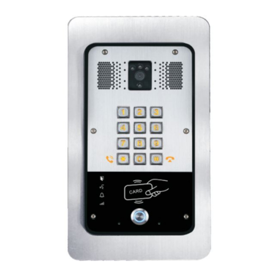
A. Product introduction DP31 is a full digital network door phone,its core part adopt mature VoIP solution(Broadcom chipset), stable and reliable performance, Hands-free adopting digital full-duplex mode, Voice loud and clear, video clear, generous appearance, solid durable, easy for installation, comfortable keypad, low power consumption. -
Page 6: Description
2. Description Buttons and icons Description Function Numeric keyboard Input password to open the door or calls. Can be set to a variety of functions, in order to programmable keys meet the needs of different occasions induction zone RFID induction area Door unlocking: On Lock Status Door locking: Off... -
Page 7: Confirm Connected
Confirm connected Confirm whether the equipment of the power cord, network cable, electric lock control line connection, the startup is normal. (Check the network state of light) 1) Power port Power supply ways: 12v/DC or POE. CN16 +12V 12V 1A/DC 2) Electric-lock and indoor switch port S_IN S_OUT... -
Page 8: Quick Setting
Driving Mode Driving Mode Jumper port Connections Passiv Active √ √ √ √ √ √ √ √ √ √ Quick Setting The product Provide a complete function and parameter setting, users may need to have the network and SIP protocol knowledge for understanding the meaning represented by all parameters. In order to let equipment users can quickly enjoy the high quality speech brought by the IP Phone... -
Page 9: Basic Operation
services and low cost advantage, we especially lists the basic and must set options in this section, which let users can real-time started without understanding complex SIP protocols. In prior to this step, please make sure your broadband Internet online can be normal operation, and complete the connection of the network hardware. -
Page 10: End Call
Configuration shortcut (key1) as hot key and setup a number, then press shortcut keys can call the configured number. 3. End call Enable Release key hang up to end call. 4. Call record The device provides 900 call records, when the storage space is exhausted, will cover the first call records. -
Page 11: Password Configuration
When the device and your computer successfully connected to the network, the on browsers enter the IP address of the device. You can see the Webpage management interface the login screen. Enter the user name and password and click [logon] button to enter the settings screen. After configuring the equipment, remember to click SAVE under the Maintenance tab. -
Page 12: B) Wizard
Status Field Name Field Name Shows the configuration information for WAN port, including connection mode of Network WAN port (Static, DHCP, PPPoE),MAC address, IP address of WAN port Accounts Shows the phone numbers and registration status for the 2 SIP LINES. b) WIZARD Wizard Field Name... -
Page 13: C) Language
PPPoE mode In this mode, you must enter your ADSL account and password. Static IP mode is selected; Click <Next> to go to Quick SIP Settings, Click Back to return to the Wizard screen. After selecting DHCP and clicking NEXT, the Quick SIP Settings screen will appear. Click Back to return to the Wizard screen. -
Page 14: Network
Time&Date Field Name Explanation System Current Time Display the current time Simple Network Time Protocol (SNTP) Settings Enable SNTP Enable or Disable SNTP Primary Server IP address of Primary SNTP Server Time zone Local Time Zone Time Format Configuration time format, the default is 24 hours. Date Format Configure date display format, the default is (date) (month) (year) Date Seperator... - Page 15 Field Name Explanation WAN Status Active IP address The current IP address of the equipment Current subnet The current Subnet Mask mask Current IP The current Gateway IP address gateway MAC address The MAC address of the equipment Field Name Explanation WAN Settings Enable Vendor...
- Page 16 Vendor Identifier Configure display Vendor Identifier Select the appropriate network mode. The equipment supports three network modes: Network parameters must be entered manually and will not change. All parameters Static are provided by the ISP. DHCP Network parameters are provided automatically by a DHCP server. PPPoE Account and Password must be input manually.
-
Page 17: B) Qos&Vlan
the default. Setting this port to 0 will disable HTTP access. Example: The IP address is 192.168.1.70 and the port value is 8090, the accessing address is http://192.168.1.70:8090. Port for HTTPS access. Before using https, an https authentication certification must be HTTPS Port downloaded into the equipment. - Page 18 Note: In practice, VLANs are distinguished by the use of VLAN IDs. QoS&VLAN Field Name Explanation Link Layer Discovery Protocol (LLDP) Settings Enable LLDP Enable or Disable Link Layer Discovery Protocol (LLDP) Enables the telephone to synchronize its VLAN data with the Network Switch. Enable Learning The telephone will automatically synchronize DSCP, 802.1p, and VLAN ID values Function...
-
Page 19: C) Web Filter
SIP DSCP Specify the value of the SIP DSCP in decimal WAN Port VLAN Settings Enable WAN Port Enable or Disable WAN Port VLAN VLAN WAN Port VLAN ID Specify the value of the WAN Port VLAN ID. Range is 0-4095 SIP 802.1P Priority Specify the value of the signal 8021.p priority. -
Page 20: Voip
Field Name Explanation Update Security Select the security file to be updated. Click the Update button to update. File Delete Security Select the security file to be deleted. Click the Delete button to Delete. File SIP TLS Files Show SIP TLS authentication certificate. HTTPS Files Show HTTPS authentication certificate. - Page 21 Field Name Explanation Basic Settings (Choose the sip line to configured) Shows registration status. If the registration is successful will display has been Status registered, not successful display not registered, the wrong password is displayed 403 errors, account number failure display timeout. Server Address SIP server IP address or URI.
- Page 22 Advanced SIP Settings Proxy Server SIP proxy server IP address or URI, (This is normally the same as the SIP Registrar Address Server) Proxy Server Port SIP Proxy server port. Normally 5060. Proxy User SIP Proxy server account. Proxy Password SIP Proxy server password.
-
Page 23: B) Stun
Protocol Enable Rport Enable/Disable support for NAT traversal via RFC3581 (Rport). Enable /disable registration with authentication. It will use the last authentication Keep field which passed authentication by server. This will decrease the load on the Authentication server if enabled Enable PRACK Enable or disable SIP PRACK function. -
Page 24: Intercom
STUN Field Name Explanation STUN NAT Traversal Shows whether or not STUN NAT Transversal was successful. Server Address STUN Server IP address Server Port STUN Server Port – Default is 3478. STUN blinding period – STUN packets are sent at this interval to keep the NAT Binding Period mapping active. -
Page 25: A) Function Key
a) FUNCTION KEY 1-4 programmable key in phone software (depend on hardware), you can configurate different feature on each key. You can ref to below indications for each feature. default is NA, means without any feature settings. Key Event Settings Set the key type to the Key Event. - Page 26 DSS key type Number Line Subtype Usage In Speed dial mode, Fill the with can define The SIP Speed Dial called whether this call is allowed to be hang up account Hot Key party’s SIP by re-press the speed dial correspondin account or g lines...
-
Page 27: B) Media
b) MEDIA This page configures audio parameters such as voice codec, speak volume, mic volume and ringer volume Field Name Explanation Audio Settings First Codec The first codec choice: G.711A/U, G.722, G.723.1, G.726-32, G.729AB Second Codec The second codec choice: G.711A/U, G.722, G.723.1, G.726-32, G.729AB, None Third Codec The third codec choice: G.711A/U, G.722, G.723.1, G.726-32, G.729AB, None Fourth Codec... - Page 28 length G.723.1 Bit Choices are 5.3kb/s or 6.3kb/s. Rate G.729AB Payload G.729AB Payload Length – Adjusts from 10 – 60 mSec. Length SPK Output Set the speaker calls the volume level. Volume Broadcast Output Set the broadcast the output volume level. Volume Signal Tone Set the audio signal the output volume level.
-
Page 29: C) Dnd
c) DND Field Name Explanation DND Methods Settings DND option Set the DND option, default is phone. DND Line Settings SIP1 Enable or Disable sip1 DND SIP2 Enable or Disable sip2 DND DND Global Settings Enable DND Enable or disable DND timer Timer DND Timer Set the DND time... -
Page 30: E) Mcast
Feature Field Name Explanation Feature Settings Ban Outgoing If enabled, no outgoing calls can be made. Speed Dial Action Default is Speed Dial Hand-down function Enable Telnet Enable or disable Telnet Select your Tone Standard configuration signal sound. Enable Intercom If enabled, mutes incoming calls during an intercom call. - Page 31 Using multicast functionality can be simple and convenient to send notice to each member of the multicast, through setting the multicast key on the device, sending multicast RTP stream to pre-configured multicast address. By on the device configuration monitoring multicast address, listen to and play the group multicast address send RTP stream.
- Page 32 session in state; If is not enabled, the device will automatically ignores all receive multicast RTP stream. Web Settings: The multicast SS priority is higher than that of EE, the highest priority. Note: when a multicast session key by multicast, multicast sender and receiver will beep. Listener configuration ...
-
Page 33: F) Action Url
the Priority is 3, group 2 and group 3 for priority level equal to 3 and less than 3 were rejected, 1 priority is 2 higher than ordinary call priority device can answer the multicast message at the same time, keep the hold the other call. ... -
Page 34: Safeguarding (Only Fully Functional Version Support This Feature)
Action URL Settings URL for various actions performed by the phone. These actions are recorded and sent as xml files to the server. Sample format is http://InternalServer /FileName.xml (5) SAFEGUARDING (Only fully functional version support this feature) - Page 35 Security Settings Field Name Explanation Input settings Input 1 Open / Close Input port1 When choosing the low level trigger (closed trigger), detect the input port 1 (low level) closed trigger. Trigger Mode When choosing the high level trigger (disconnected trigger), detect the input port 1 (high level) disconnected trigger.
-
Page 36: Door Phone
Received the terminal equipment to send the DTMF password, if By duration correct, which triggers the corresponding output port (The Port level time change, By < Output Duration > control) Remote DTMF During the call, receive the terminal equipment to send the DTMF trigger By Calling password, if correct, which triggers the corresponding output port (The... -
Page 37: A) Door Phone
Remote Remote door unlocking password. Password Local door unlocking password via keypad, the default password Local Password 6789 length is 4. DP31 Video Sip Description Device description displayed on IP scanning tool software. Door phone Field Name Explanation Initial Value Enable Access Enable Access Table: enter <Access Code>... -
Page 38: B) Door Card
Table calls. Disable Access Table: enter <Remote Password> for opening door during calls. <Primary /Secondary>mode allow system to call primary extension first, if there were no answer, it would cancel the call and then call Hot Key Dialed secondary extension automatically. Primary Mode <Day/Night>mode allow system to check the calling time is belong to... - Page 39 Door Card Field Name Explanation Door Card Table Index The serial number of has been issuer cards. Name The name of has been issuer cards. The card number of has been issuer cards. (Note: The card is not registered in the remote access list is unable to open the door.) Issuing Date The issuing date of has been issuer cards.
-
Page 40: C) Door Access
Add Administrator ID: admin card the card number. Type: Issuer and Revoking. Entrance guard in normal state, brush card(issuing card) entrance guard into the issuing state, and then brush to add a card, the card is added to the database, add swipe again after card(issuing card) entrance guard returned to normal. -
Page 41: D) Door Log
to delete operation. Add Access Rule You can add new access rules, or select an existing project within the list to modify Name(necessary User name Department Card holder's department Position Card holder's position RFID card number Valid for user access rules (including RFID, access code, etc) within corresponding Time Profile time section. -
Page 42: Maintenance
Field Name Explanation Door Opening Log Result Show the results of door opening Door Opening Open the door of time. Time Duration Duration of open the door. Access Name If is the open the door for slot card or remote, will display remote access the name. 1. - Page 43 The equipment supports PnP, DHCP, and Phone Flash to obtain configuration parameters. They will be queried in the following order when the equipment boots. DHCP option → PnP server → Phone Flash Field Name Explanation Auto Provision Settings Show the current config file’s version. If the version of configuration downloaded is Current Config higher than this, the configuration will be upgraded.
- Page 44 Check Times Save Auto Save the auto provision username and password in the phone until the server url Provision changes Information Download CommonConfig Enable or disable download commonconfig enabled Download DeviceConfig Enable or disable download deviceconfig enabled DHCP Option Settings DHCP Option The equipment supports configuration from Option 43, Option 66, or a Custom DHCP Setting...
-
Page 45: B) Syslog
Enable TR069 Enable/Disable TR069 configuration Enable TR069 Enable or disable TR069 Warning Tone Warning Tone ACS Server Type Select Common or CTC ACS Server Type. ACS Server URL ACS Server URL. ACS User User name for ACS. ACS Password ACS Password. TR069 Auto Enable/Disable TR069 Auto Login. -
Page 46: C) Config
System log settings Server Address System log server IP address. Server port System log server port. MGR log level Set the level of MGR log. SIP log level Set the level of SIP log. Enable syslog Enable or disable system log. Web Capture Capture a packet stream from the equipment. -
Page 47: D) Update
Reset To reset the system and Automatic restart the equipment. Configuration d) UPDATE This page allows uploading configuration files to the equipment. Field Name Explanation Browse to the config file, and press Update to load it to the equipment. Various types Web Update of files can be loaded here including firmware, ring tones, local phonebook and config files in either text or xml format. -
Page 48: F) Reboot
Field Name Explanation User Settings User shows the current user name Show the user level; admin user can modify the configuration. General user can only User level read the configuration. Add User User Set User Account name Password Set the password Confirm Confirm the password There are two levels. -
Page 49: Appendix
Click <Logout> from the web, visit next time when need to enter your user name and password. E. Appendix 1. Technical parameters... -
Page 50: Basic Functions
Communication protocol SIP 2.0(RFC-3261) Main chipset Freescale i.MX 6Quad DSS key materials Stainless steel DSS Key 1 or 2 Numeric keyboard Support Audio amplifier Volume control Adjustable Full duplex speakerphone Support (AEC) Audio DTMF TYPE In-band, Out-of-band(RFC 2833), SIP INFO wideband speech code G.722 Narrowband speech code... -
Page 51: Schematic Diagram
Intelligent DSS Keys (Speed Dial/intercom etc) Wall mounted / In-wall Special integrated noise reduction module Dual microphone Omnidirectional voice pickup Integrated RFID Card reader 1 indoor switch interface 1 electric lock relay Anti-tamper switch ... -
Page 52: Management Of Card
2) Private access code Set <Add Access Rule\Access Code> and enable local authentication. Use the device's keypad to input access code and "#" key, then the door will be unlocked. Remote Visitors call to owner Visitors call to owner via position speed dial or phone number. (When set the speed dial key, can press it to call direct.) ... - Page 53 2) Add<Revocation admin card> Input a card’s ID, selected <Revocation> in the types and Clicked <Add>, you can add Revocation admin card. 3) Administrator Table Delete Administrator Select the admin card of need to delete, click <Delete>. Add user cards Method 1: used to add cards for starters typically 1) In web page <...
- Page 54 Methods 2: use to add few cards 1) Input cards number in door card settings page, and then click <Add>. Note: you can also use the USB card reader connected with PC to get cards ID automatically. Only need input the before 10 Numbers. Method 3: used to add cards for professionals 1) Use <Issuer admin card>...
- Page 55 3) Use card to touch card reader induction area, and you might hear the card reader confirmed indication tone. Repeat step 3 to delete more cards. 4) In web page <Door card →card reader Settings >option, select <normal>. 5) Click <Apply>, Card Reader would be back to the Normal status. Method 2: used to batch add cards for intermediates.
Need help?
Do you have a question about the DP31 and is the answer not in the manual?
Questions and answers